That's not to mention that there's an output transformer in the equation that is probably down 3dB at 50kHz.40pF is an impedance of 199k at 20kHz. The Rp of a 45 is about 4k.
Gentlemen - in light of the concerns raised regarding 6W across the output CCS, I have been investigating a pentode CCS solution as an alternative. While I'm aware that they do not perform as well as the MOSFET/BJT cascodes, I wonder how significant the real-world audible difference would be...
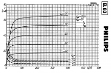
Anyhow, my top contender after reviewing many resources is the EL83, curves below for 170V on g2. Aiming for a g2+cathode current of ~31, I believe a -3V g1 28mA bias point would work, this would give a Ig2 of ~3.8mA, bringing the total at the cathode to ~31.8mA.

Dropout voltage on the -3V g1 curve is ~60V. I think this is okay with my 400V B+ using a 5K/16 OPT if a resistor is used in parallel with the output, which would give me well over 100V of headroom. If no paralleled resistor and looking at a flat load line, peak voltage swing on the negative grid curve leaves only 75V of headroom. If I go down this route, I may just bump the mains transformer HT secondary up 10% or so for the flexibility to experiment.
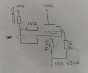
Here is a draft schematic of the EL83 CCS, please let me know if anything is out of place, took myself on a 24hour crash course on pentode CCS. 60.5K dropping resistor to get 170V on g2 at 3.8mA, 1K grid stoppers on g1 and g2, bypass cap between g2 and cathode, cathode resistor value will need to be tweaked, perhaps a quality variable resistor here to fine tune output current?
Internal resistance of the EL83 in this setup is around 270K, however, it was pointed out to me the bypass cap and dropping resistor are in parallel, so the CCS becomes a reactive load and the impedance will be quite a bit lower.

Anyhow, my top contender after reviewing many resources is the EL83, curves below for 170V on g2. Aiming for a g2+cathode current of ~31, I believe a -3V g1 28mA bias point would work, this would give a Ig2 of ~3.8mA, bringing the total at the cathode to ~31.8mA.

Dropout voltage on the -3V g1 curve is ~60V. I think this is okay with my 400V B+ using a 5K/16 OPT if a resistor is used in parallel with the output, which would give me well over 100V of headroom. If no paralleled resistor and looking at a flat load line, peak voltage swing on the negative grid curve leaves only 75V of headroom. If I go down this route, I may just bump the mains transformer HT secondary up 10% or so for the flexibility to experiment.
Here is a draft schematic of the EL83 CCS, please let me know if anything is out of place, took myself on a 24hour crash course on pentode CCS. 60.5K dropping resistor to get 170V on g2 at 3.8mA, 1K grid stoppers on g1 and g2, bypass cap between g2 and cathode, cathode resistor value will need to be tweaked, perhaps a quality variable resistor here to fine tune output current?
Internal resistance of the EL83 in this setup is around 270K, however, it was pointed out to me the bypass cap and dropping resistor are in parallel, so the CCS becomes a reactive load and the impedance will be quite a bit lower.

Last edited: