I got this odd amp from a 1960 kimball organ. It uses a seperate power supply just for the 6.3vac for the heaters that uses a selenium diode. It seems to be used as a surge suppressor I think. There are two wires comming directly from the power transformer to each selenium plate and one wire from the center shaft wired directly to chassis ground. I understand these selenium devices can be quite dangerous and I would like to eliminate it. How do I determine what diodes and resistors I need to replace this thing safely?


I dont think its a rectifier as there is no DC output. Wall voltage in, 6.3v AC out. What type of diode is safe to use as a replacement?
I dont think its a rectifier as there is no DC output. Wall voltage in, 6.3v AC out. What type of diode is safe to use as a replacement?
OK, it's a BROKEN Selenium rectifier 😛
Hi,
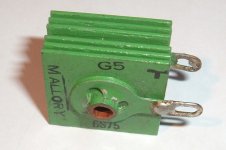
Are you referring those two red cans in the pictures? If that what it is you are referring those are capacitors. The selenium rectifier are like a five to 6 square fins holding together by a screw in the middle. The are normally orange or green color. Attached it is a picture showing it.
Are you referring those two red cans in the pictures? If that what it is you are referring those are capacitors. The selenium rectifier are like a five to 6 square fins holding together by a screw in the middle. The are normally orange or green color. Attached it is a picture showing it.
Attachments
Whenever and wherever selenium rectifiers are found, immediate replacement with modern SS diodes is mandatory. Sooner or later, selenium rectifiers fail. When they fail, toxic fumes and dust are produced. 🙁 Eliminate ticking time bombs, before they go off.
My hunch is that the OP's unit has a full wave bridge in it and 4X low noise diodes are needed, along with a resistor to compensate for a smaller forward drop in modern parts.
My hunch is that the OP's unit has a full wave bridge in it and 4X low noise diodes are needed, along with a resistor to compensate for a smaller forward drop in modern parts.
No, I am refering to the two large rectangular green plates next to the caps. Sorry, the pics are so dark. My olds notes I had packed away with this amp stated a 6.3v AC output but I re-checked and its actually 10v DC to the amp where it runs thru a coil spring looking resitor then on to the heaters.Hi,
Are you referring those two red cans in the pictures? If that what it is you are referring those are capacitors. The selenium rectifier are like a five to 6 square fins holding together by a screw in the middle. The are normally orange or green color. Attached it is a picture showing it.
Selenium diodes have a higher voltage drop compared to silicon. You may need to add a small resistor.
How would I arrange the diodes and resistors? I have two green wires for the PT to the selenium rectifier and one wire wire from the rectifer to ground, and finally one wire from the PT carrying the 10v DC. I have been reading up on replacing selenium rectifiers but cant find a circuit like this one where the DC comes from the PT.
Sounds like a "voltage doubler". The basic idea is to remove the selenium rectifiers, install silicon rectifiers in their places, and (often) add a small-value resistor in series with the output to adjust the voltage into the correct range. Maybe start by tracing out this power supply's circuit, and folks will be better able to make specific recommendations.
All good fortune,
Chris
All good fortune,
Chris
After taking a good look at your (poor) pictures, what you have is a basic full wave rectifier circuit. The difference is that the manufacturer chose to put the rectifiers on the ground side instead of the high side. What you need to do is determine the polarity of the selenium rectifier. That is, is the positive at ground, or the negative? Maybe the rectifier is marked. If not, measure the output from the transformer to ground to get the polarity. Or if there is a filter capacitor, check it's polarity to ground.How would I arrange the diodes and resistors? I have two green wires for the PT to the selenium rectifier and one wire wire from the rectifer to ground, and finally one wire from the PT carrying the 10v DC. I have been reading up on replacing selenium rectifiers but cant find a circuit like this one where the DC comes from the PT.
Once you know the polarity, then replace the selenium stack with two silicone diodes. I would use 3 amp diodes or perhaps part of a bridge rectifier block mounted to the chassis. The compensating resistor can be either between the two diodes and ground, or in the wire that comes from the transformer with the DC on it. Either way will work correctly.
Now as to what value and wattage resistor you will need, I cannot tell you because I don't know what the circuit involves. That means, how many tubes are being powered and what their current draw is. You will have to use simple ohm's law to calculate the value. (R=E÷I) Or you could guess and measure voltage and then make corrections. Maybe start with 10 or 15 ohms (5 watts) and work from there.
I understand how this is usually done with two or four silicon diodes and a resistor, the problem I have now is that there is no obvious AC in DC out paths to place them. The entire circiut is as simply 120v AC into the PT and three leads out from the PT. Two go to the selenium rectifier and the other puts out the 10v DC which then goes thru two large chokes and caps then to the amp.. The rectifier has only three leads connected to it, two from the PT and one to the chassis ground. So far all the schematics I have seen show AC going to the rectifier and DC going out, my DC out comes out of the PT. So I guess I have my AC and DC on the same leads. Can I just connect two PT leads to a SS rectifier then connect the DC output to the chassis ground and to the choke where the PT DC output was connected?
I never forget the penetrant 'garlic' odour of those industrial selenium rectifiers that I worked on some 40 years ago...
It sounds like you have the standard two-diode full-wave rectifier using a centre-tapped transformer secondary. The only unusual thing is that the rectifer is at the ground end with the supply taken from the secondary CT rather than the other way round. You can retain this arrangement or not, up to you. Just remember to swap the diode direction if the DC polarity is important.
Both diodes need to be the same way round. I assume that the big caps in your picture are electrolytics to smooth the heater supply? If so, you need to ensure that the DC polarity is correct.
Do you know what the full-wave two-diode circuit looks like? It was the normal method used with vacuum rectifiers. Your circuit is the same, except that the diodes and transformer have swapped places. This is OK, as they are effectively in series. Another way to think of it is that the normal circuit has been turned upside-down.
If you know about diodes then there should be no problem. If not, get someone else to do it for you.
Well,
The best thing that ever happened when they replaced selenium with silicon..
Oh whats that smell...not to worry just the rectifier again

 I only changed it last week...
On the other hand some seemed to run for ever and just get more Tanned with age...still a PITA..and why did they always twist the cable round them like a pigs tail so you needed a blow torch to get them off as the insulation melted with the burn out...
I must add as Hollowstate says...were you riding a mechanical Bull in the dark when you took the Photos... 😀
Regards
M. Gregg
The best thing that ever happened when they replaced selenium with silicon..
Oh whats that smell...not to worry just the rectifier again
I only changed it last week...On the other hand some seemed to run for ever and just get more Tanned with age...still a PITA..and why did they always twist the cable round them like a pigs tail so you needed a blow torch to get them off as the insulation melted with the burn out...
I must add as Hollowstate says...were you riding a mechanical Bull in the dark when you took the Photos... 😀
Regards
M. Gregg
Last edited:
I am still unclear as to how the diodes should be arranged in this circuit.
TR1, L1, L2, C1 and C2 are existing in your circuit. Remove selenium rectifier and add D1, D2, and R1. Select R1 to get the correct voltage on the output at the proper load.
There appears to be a clay colored thing (capacitor?) connected at the CT of the transformer secondary and chassis gnd. I think it should be retained for noise filtering.
edit: BTW, if you want to retain the original look, you can keep the selenium rectifier mounted but unconnected and hide the new diodes inside the chassis.
Attachments

Last edited:
TR1, L1, L2, C1 and C2 are existing in your circuit. Remove selenium rectifier and add D1, D2, and R1. Select R1 to get the correct voltage on the output at the proper load.
There appears to be a clay colored thing (capacitor?) connected at the CT of the transformer secondary and chassis gnd. I think it should be retained for noise filtering.
edit: BTW, if you want to retain the original look, you can keep the selenium rectifier mounted but unconnected and hide the new diodes inside the chassis.
Thats kinda what I thought from the written responses but I was unsure. Your schematic makes things much more clear to me now. Thanks for the input everyone.
- Status
- Not open for further replies.
- Home
- Design & Build
- Parts
- selenium diodes