At least separate bias means you can get the bias right.
And minimize DC in the output transformer.
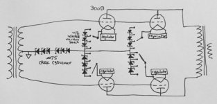
I just posted this in another thread, but how about this schematic for output stages designed to always remain in class A?
The dynamic impedance of the shared diode series is ~75Ohms, which should minimize distortion from imperfect cancellation of push-pull cathode current. The rotary switch selectable diode series in each cathode allows for matching of quiescent current, also with minimal dynamic impedance in the cathode.
The dynamic impedance of the shared diode series is ~75Ohms, which should minimize distortion from imperfect cancellation of push-pull cathode current. The rotary switch selectable diode series in each cathode allows for matching of quiescent current, also with minimal dynamic impedance in the cathode.
Attachments
cerrem,
Good for you. I think I only know of one other person that has told me he did a A to AB current study.
I am not sure what probes, etc. you were able to use.
And for those who want to do this experiment, there are some hints:
At work, I had access to current probes that went all the way down to DC. An AC current probe will not work properly for the A to AB test.
And another main point is that you need 2 DC current probes (or 2 sense resistors), and you view 'push' and 'pull' at the same time on a 2 channel scope in DC coupled mode. That gives a really good picture of what is going on.
But at home I merely used cathode sense resistors, and a 2 channel scope in DC coupled mode.
Yes, some sort of individual bias is important. And yes, having equal quiescent currents on the push and pull halves of the output transformers is important.
In many push pull circuits, you will find that you have already left the class A region, and already gone to the class AB region before you go into clipping.
That is why I asked how many of you had done sense resistor current studies to see where that A to AB occurs in your amp. Then go and see if you are not yet into clipping. The tube that is headed toward cutoff has current that goes flat earlier than you would expect (that tube's rp is increasing, and/or grid curves are compressing, etc.).
I assumed you were talking of non-monotonic characteristic curves, not non-monotonic performance curves.6A3sUMMER said:Look at the very bottom graph. You will see very sharp, and very deep nulls of the third harmonic distortion as the load impedance changes.
That tube "curve" is extremely non-monotonic.
In many push pull circuits, you will find that you have already left the class A region, and already gone to the class AB region before you go into clipping.
I wouldn't use the term, many, there. That is the way it's supposed to work in all AB amps. Cuttoff occurs by design on one side and clipping only occurs if the drive signal pushes up to create more than 0v on the grid. If clipping occurs before cuttoff then you have a mis-biasing condition.
Last edited:
A 6B4G or 2A3 with 250V across it, and 60ma quiescent has 800 Ohms rp, and u = 4.2. Put a 10 Ohm resistor in series from the filament circuit to ground. The plate resistance, rp, will increase by 10 x 4.2 = 42 Ohms. The new rp is 842 Ohms (only about 5% larger). A 10 Ohm current sense resistor in the filament circuit to ground will have 600mV across it. An inexpensive DMM should be able to read that 600mV reasonably accurately. Even if it is a little bit inaccurate, it will have the same error for reading two equal 600mV points. As you adjust the bias of the push and pull tubes to match the currents, then 1% 10 Ohm resistors will allow a current match of 2%, when you match the 600mV readings. That is 1.2 mA difference in the output transformer secondary halves.
Last edited:
A resistor which is significantly smaller than 1/gm will do no harm.
I should know this, but could you clarify for me?
gm in mhos or mmhos? I figure it's mhos (mA/V) but not certain.
kodabmx,
For transconductance, use the fundamental unit of Siemens. Siemens are Mhos. millimhos are thousandths of a Mho micromhos are millionths of a Mho. But Mhos are inconvenient for most tubes, so we often use units of micromhos (umhos). Examples:
A 2A3 has 5,500 umhos of transconductance. That is 5,500 x ((10)^(-6)) Siemens; or 5,500 x ((10)^(-6)) Mhos.
1/5,500 uMhos = 181 Ohms, that is the impedance of the filamentary "cathode" when the plate load is zero Ohms.
If the plate load was zero Ohms, and a 10 Ohm sense resistor is inserted from the filament to ground, you have the signal voltage on the grid divided by: 180 Ohms/(180 Ohms +10 Ohms) = 94.7% of the grid signal is across the transconductance of the filamentary cathode, and 5.3% is developed across the 10 Ohm resistor.
When the plate has a real load, the filamentary cathode impedance rises.
A 2A3 that has a plate load of 3k will have a filamentary cathode impedance:
180 Ohms + 3k Ohms/(u +1) = 3k Ohms/(4.2 +1) = 3k Ohms/5.2 = 577 Ohms
180 Ohms + 577 Ohms = 757 Ohms filamentary cathode impedance.
Now, the new voltage divider is 577 Ohms and the 10 Ohm sense resistor. 10/(577 + 10) = 1.7% across of the signal across the 10 Ohm resistor It is not a problem to use an unbypassed 10 Ohm current sense resistor here.
Last edited:
It doesn't matter. You can use whatever units you like, as long as you know which units you used. If gm is in millimhos then the resistance is in kilohms. If gm is micromhos then resistance is in megohms. In Europe we tend to use mA/V so the resistance is K.kodabmx said:gm in mhos or mmhos? I figure it's mhos (mA/V) but not certain.
kodabmx,
A 2A3 has 5,500 umhos of transconductance. That is 5,500 x ((10)^(-6)) Siemens; or 5,500 x ((10)^(-6)) Mhos.
Is it any different for indirectly heated triodes? How about (beam) tetrodes?
kodabmx,
Good question!
Transconductance = Transconductance
Amps/Volt
Directly Heated, and Indirectly Heated; Transconductance, Gm = Gm.
Beam Power, Pentode, Triode and True Tetrode.
True Tetrode is where we get into some naming trouble.
A True Tetrode does not have a suppressor screen (a Pentode does).
A True Tetrode does not have Beam Forming plates (a Beam Power tube does).
A True Tetrode has a filament or filament and cathode; a control grid; a screen grid, and a plate.
The direct heated filament 'cathode', or indirectly heated cathode does not connect to any other element. And there is not another element.
Many True Tetrodes use Beam Forming techniques.
Consider 2 round 'bird cages', the bigger one placed over the smaller one (but not touching). Those 'bird cages' have exactly the same number of vertical wires.
They are aligned rotationally, so that you can see straight through the 2 sets of vertical wires.
The filament, or filament and cathode are inside the smaller 'bird cage". The plate is circular and placed around the outer 'bird cage'.
The alignment of the 2 'bird cages' causes sheets of electron flow (beams).
An example of a directly heated true tetrode is a 4-65A. It does use those aligned 'bird cages'.
A long time ago, some called a 'Beam Power' tube that has beam forming plate(s), a 'Beam Tetrode' (sheet beams tetrode).
But the two are not the same.
This thread was started about a 6B4G amplifier, using 2A3 operating points.
That is why I used the well known 2A3 as an example for transconductance, cathode impedance, plate impedance, etc.
Last edited:
Keep in mind that gm is not a constant .....use a value based on the "average" gm over a tube's operating cycle.... In Class A, it averages closely to what it is at idle...close enough...
Also....when you have an inductive load in the plate....impedance looking into cathode is more like r+jw ....
Also....when you have an inductive load in the plate....impedance looking into cathode is more like r+jw ....
My amp is push-pull 6B4G. I am currently using a shared cathode resistor. The output tubes are plate current matched using a wee bit of fixed bias and operate in class A using the classic 2A3 SE operating point. Is having a shared cathode resistor a poor idea in my situation?
I understand that you want to avoid current mismatches in the output transformer that results from running class AB or from mis-matched tubes. But as I address these is there any reason NOT to use a shared, unbypassed cathode resistor?
Rod
There’s nothing wrong with a shared cathode resistor, it’s part of what accounts for the excellent sound of a Williamson. I leave mine unbypassed, it just sounds better. While you’re at it you might look at the Williamson biasing circuit. It uses a balance pot to send a little positive voltage to each grid, enabling you to match the outputs very closely. I used it in my PP 300B amps and it worked very well. Avoids the extra negative bias supply. I used these 100 ohm pots, they’re perfect:
2pcs 100 OHM 5W Wirewound Potentiometer, Pots, 5 Watt. 5W . 6921407452893 | eBay
Then I add 30 ohms/2W from each cathode to the top of the main bias resistor. Add test points at the cathodes, measure across them and zero out the voltage difference with the balance pot.
Last edited:
When a loudspeaker system is connected to the output transformer, it reflects capacitive, resistive (can be different than the output secondary tap's rated value), as well as inductive loads back to the plate. And that "reflects" back to the cathode. Therefore, the cathode impedance can vary a lot over the audio band. The combinations of RLC are many. Just more to consider.
grovergardner,
Very interesting.
I believe most Williamson amps use global negative feedback. It tends to make up for some of the internal distortions of the amp.
Have you done a study of 2nd and 3rd harmonic distortion with, and without, a bypass cap across the shared bias resistor? Into a resistive load? Into your loudspeaker (at low or moderate power, class A region)?
Is the shared resistor on one channel, or shared between left and right channels?
No, I have not done a study of distortion characteristics, except with my ears. ") . I prefer my Williamsons without the bypass caps. I assume with my old ProAcs they are probably pushing the limits of 12 watts with some music.
. I prefer my Williamsons without the bypass caps. I assume with my old ProAcs they are probably pushing the limits of 12 watts with some music.
I assumed the OP was referring to sharing a cathode resistor between two tubes in a PP circuit.
. I prefer my Williamsons without the bypass caps. I assume with my old ProAcs they are probably pushing the limits of 12 watts with some music.I assumed the OP was referring to sharing a cathode resistor between two tubes in a PP circuit.
grovegardner,
You give me food for thought . . . trying push pull and a common cathode resistor without a bypass cap.
I need to think more about the transition region from class A to class AB; and then the
possibility of softer clipping too.
I have some ProAc speakers.
What ProAc model do you have?
You give me food for thought . . . trying push pull and a common cathode resistor without a bypass cap.
I need to think more about the transition region from class A to class AB; and then the
possibility of softer clipping too.
I have some ProAc speakers.
What ProAc model do you have?
The summed cathode currents of a pair of push-pull valves increases (somewhat) with signal level, so it has an "envelope" of current varying with time. If we add a capacitor we modify this envelope in a simple, predictable way. We care about it because it sets the bias of the output valves.
There are no ideal choices for anything except the simplest and most linear case (very lightly loaded class A). It's a small step from there to using adjustable "fixed" bias for any other output stage.
All good fortune,
Chris
There are no ideal choices for anything except the simplest and most linear case (very lightly loaded class A). It's a small step from there to using adjustable "fixed" bias for any other output stage.
All good fortune,
Chris
- Status
- This old topic is closed. If you want to reopen this topic, contact a moderator using the "Report Post" button.
- Home
- Amplifiers
- Tubes / Valves
- Shared cathode resistor - always sub-optimum