Hi Bruno.
I have build Elvees Circlophone with Terranigma MosFet Board.
You have 2N3055 and KD503 on Hand- look the normal BJT Circlophone- Elvee started
All is fixed by Resistor Size.
A nice sounding Amp- powerful.
Building Elvee's Circlophone: Documentation, Parts, Accessories, & beginner friendly
Cheers Bangla.
Hello, After a long time, I made the pcb my self , the amp sounds pretty good , especially the mids and highs.. BUT it distorts on bass , I manage to pull out 20w with no distortion , after that it sounds distorted , what might be the problem ?
The transformer is big enough, Tryed it with 2n3055's and TIP35's still distorts after 20-25w, Quis current 50, tryed 100 and even more, after 100 it didnt distorded a bit less but STILL did...
you said something about D3-D6 are for limitting the current , will it help to pull them out ?
Thanks.
The transformer is big enough, Tryed it with 2n3055's and TIP35's still distorts after 20-25w, Quis current 50, tryed 100 and even more, after 100 it didnt distorded a bit less but STILL did...
you said something about D3-D6 are for limitting the current , will it help to pull them out ?
Thanks.
Is the distortion on speakers or headphones?
Look at your rail voltages while the distortion is happening.
High ESR used rail capacitors can have a damping effect on bass particularly. I work on geriatric electronic organs, where this effect is all too frequent whatever the amp design. Low rail capacitance can also be a problem. I'm running 3300 uf for two channels single output select high Vce 2n3055 original, now MJ15003. My bass is fine, on the AX6 circuit I just built.
Ordinarily inadequate output idle current causes distortion at low wattage, not high.
You may also have too much gain, and be driving the output into clipping. Is this board the original Elektor design or the Ron Elliott P3 design? Are your rails +-35 v under all states? Notice DVM average over 2 to 4 seconds, you'll miss transients using one of those. Use an analog VOM for fast response time.
While you're at it, check for AC voltage out (.047 uf blocker cap on negative probe) with analog VOM while idle. If amp is oscillating ultrasonically it messes up the sound. You can also use a 390 pf blocker cap on negative probe of analog VOM to isolate ultrasonics (pass) from audible sound (blocked by cap).
With a scope ultrasonics make a fuzzy waveform, or low period waveforms if your trigger circuits are better than the televideo scope I owned.
D3-D6 on original design are VI limiters, which sound awful when they kick in. My AX6 and original dynaco ST120 don't have them. I limit current by the kind of music I play. Classical music is not loud for very long. Rock/pop/techno can have high volume all the time, and single 2n3055 don't have much SOA to handle long periods of high wattage. 30 W into 4 ohm speakers for very long probably can burn 2n3055 up. 8 ohm they might make it. Are your 2n3055 RCA/Delco/Sprague homotaxial originals from 1970-76 or epitaxial copies from later? Current ON semi parts marked 2n3055 are a different part entirely.
Last edited:
The amp is first picture in this thread, not Rod Elliott's amp!
Measured today, on my subwoofer 400w rms (car sub from Pioneer..so i know for shure the speaker isn't distorting)
Results: after 4v output it distorts, in 2 ohm, around 8 watts, the transformer is pretty big, 5amps per rail (only one channel, one amp not two on the same transformer) caps are 6800uF 60v, +-35v supply, it draws 1.5amps per rail aprox and it distorts..
Didn't measure the power draw on the rails tho, but Max I've got 14v in 2 ohms - 98 w or so with pretty high distortion
I didnt remove the diodes D3-D4-D5-D6, aren't they for biasing ( BE junctionof T11, T12?
Thanks.
I think T9-T10 plus pot are for biasing, splitting the voltage between upper drive and lower drive by 3 or 4 diode drop voltages. It appears T9-T10 should be mounted on the output heat sink to automatically drop the split voltage as the heat sink heats up.
2 Ohm speakers are way below the current capability of a single 2n3055 pair. Especially at +-35 v rail, which is over the max the original homotaxial parts are designed for.
Personally, the DVM I use both produce random numbers on music on the AC scales. If you are using an analog meter or a Fluke RMS specified DVM, the numbers may be real.
I'm getting significant volume peaks out of my single pair of MJ15003, (NTE60) although I never had any original 2n3055 to listen to. they were burnt up when I bought the amp. This was a 60 w/ch amp though, limited mainly by the ****y heat sinks to a limited time wattage rating.
You could measure peak voltage while distorting with a fast response meter or scope across D3-D4, or D5-D6, to see if they are doing anything. More than 1.3 v peaks, they are active. Dual slope DVM measurements averaging over 2 to 4 seconds are not interesting. I think d3-d6 are for current clampling.
6800 uf rail caps should be okay, if the caps are new. Since you laid the board out yourself, rail impedance may be a limiter. I'm using 22 ga wire for my output transistor wiring, also rail cap to rectifier. That is .000642 square inch of copper. Make sure your traces to the collector and emitter of the output transistor have that much area. You should measure the minimum voltage at the collector when the distortion is occurring. Peak results only, no dual slope DVM average readings.
If you're using BD139-140 as driver, if you put a heat sink on them they will drive two pairs of output transistors. Double up the emitter resistors also, one for each output transistor.
My transformer will deliver 7 amps to two channels at 80v, or 560 VA.
The amp didn't got hot on 2ohm, also on 8ohm it distorts, the traces are 4mm thick at least, I think is enough, what does current clamping mean you said that's what d3-d6 do. Also even 30ohm on the pot nringws the quisance current to 600mA i can't set it "smoothly" this didn't happend first time i' be build it, this weird thing appeared for no reason.
I will try tomorrow again with D3-D6 left out..
Thanks for help..
Do you think changing the output too complementary would help? I own some 2sc/2sa pairs 120w 10 amps or soo. But this chircit claimed to be 60w at least, and i only get 10-20 w without distortion. Something must be wrong here, my 2n3055 are old 1988, tryed 2sc5200 same thing,
Also why is C3 C4 C5 3x 820nano (2460 uF) non polarised and there is not one polarised cap with - on gnd around 20-100 uF like I saw on many other designs?
I know that cap changes the frequency response ( first time I ve started it i' be put accidentally 2,2 nano LOL not 2.4 uF and below 200hz it was dead, now I have one 2.2uF non polarised. Do you think if I change that cap with one electrolytic 20-100uF will fix my "distortion problem? . I will try anyway cuz Im curious what will happen.
I know that cap changes the frequency response ( first time I ve started it i' be put accidentally 2,2 nano LOL not 2.4 uF and below 200hz it was dead, now I have one 2.2uF non polarised. Do you think if I change that cap with one electrolytic 20-100uF will fix my "distortion problem? . I will try anyway cuz Im curious what will happen.
C3 C4 C5 are anti-oscillation parts in the feed back loop. they should be ceramic caps to filter out ultrasonics, not non-polar electrolytic caps. electrolytics are wound and have too much inductance at 1 mhz up. Don't mix nf and uf. You couldn't buy 2.2 uf ceramic caps in 1985 is why he used 3 820 nf, , you can now get 2.2 uf ceramics for about $1. Be sure any 2.2 uf ceramic you buy is 50 rated or higher.
About the 100 uf caps in the front end. This elektor amp uses constant current sources T5 & T6 , not a voltage regulator like a dropping resistor & capacitor combination like my AX6 board uses.
The best place for a 20 to 1000 uf non polar cap is from the base line of T11 to T12, that will smooth out your bias jumping problems which are probably pot wiper related. Pots don't last very long, the wipers oxidize, I tend to use them for test then replace them with a fixed resistor before I put the cover on.
Changing from quasi comp to full comp won't change anything IMHO. I've got a qsasi comp ST120 with djoffe bias modification that sounds just like my full comp CS800s at the 1/4 watt base level of my music room. You've got to reconfigure the drivers for full comp, anyway. More transistors is the textbook answer for 2 ohm speakers. If you want to go off board with 3 or 4 pair output transistors, change drivers from BD139/140 to MJE15028/29. If you don't want totally pure tinkly bells, I'm using TIP41C/42C $.38 each for drivers, with heatsinks. Sound great except for the very highest of tinkly bells. Where are you? There are a lot of 2sa# 2sc# drivers that I can't buy in this country with an actual heat sink tab. Driver transistors for multiple output transistors need to have wattage of 20 up and Ft of 30 mhz or higher to do tinkly bells. See this link for a list of driver transistors greg erskine can buy in Australia. http://users.tpg.com.au/gerskine/greg/driver%20transistors.htm
I still think you are current limiting and clipping. My 560 VA transformer wouldn't begin to supply current to a 2 ohm speaker. 3.5 amps per channel my transformer will supply is only 25 watts at 2 ohms. How many VA is your transformer? Also, 2n3055 aren't much use above 2 amps continuous, or 8watts. Case temperature doesn't mean very much, transistors do second breakdown because of die temperature which you can't measure. Your transformer at +-35 is set up for an 8 ohm speaker, not a 2 ohm. How many VA is it? If this is a dedicated 2 ohm amp, you need lower voltage and more current transformer.
You need to measure the thickness of the traces times the 4 mm to know what square mills of copper you have. cheap PCB aren't usually very thick.
However, 1985 2n3055 have Ft of 4 mhz and will oscillate pretty freely. One thing modern builders do to old designs for 400 khz Ft 2n3055 is put a 10 ohm "base stopper" resistors between collector of drivers T13 T14 and bases of output transistors T15 T16. You haven't done the oscillation checks with an analog meter or scope yet, right? You can get an analog meter with 50 vAC scales at the hardware store for about $25 I think.
Best of luck. Off to the project until evening.
Best of luck.
Last edited:
Hi xXBrunoXx,
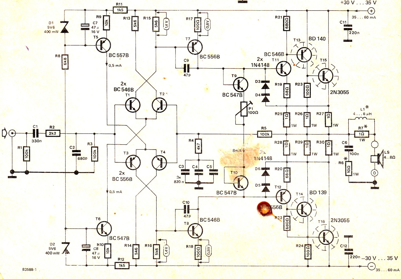
I think this amplifier definitely deserves to be listened to. It is a 1982 Elektor Summer Circuits project. It has been discussed here in DiyAudio quite few times. If you want to read about it, search for "amplifier based on 2N3055"
keywords in DiyAudio. If you want to build it, make sure that you don't employ modern, fast transistors for the output, it might oscillate. I have built quite few copies of this amp, both metal can and plastic output transistors. The best I have found so far are MJ15003 and MJ15004 types. By the way, I have PCB's for this amp, with some minor tweaks. In my version, the outputs are complementary and the diff amps at the input have emitter resistors, and the supplies to the early stages are RC filtered, as well as the reference voltages for tails. If you want to try my version, please contact me at selim_ardali at yahoo dot com.
As for temperature compensation, the outputs are triples and the first transistors in the triples, "BC546 and BC556" remain absolutely cool in operation. Thus, the output stage is immune to temperature changes.
Best Regards
Selim
C3 C4 C5 are there to increase feedback at DC so you will get a low offset voltage, when I built this amp 1987 I experimented with the value and I also shorted them out because I thought I got to much phase shift at low frequencies. It is possible to increase the capacitance significantly if you wish, as you observed the value of this capacitor in other designs is very much larger.
How do you measure distortion? In 2 ohms the current limit will cut at low power and it is also an unsuitable load for this amplifier. Start by giving the amp a light load say 22ohms and 1kHz and see if you get full voltage swing at the output, if you do lower the load resistance and see if you have a current limit problem.
How do you measure distortion? In 2 ohms the current limit will cut at low power and it is also an unsuitable load for this amplifier. Start by giving the amp a light load say 22ohms and 1kHz and see if you get full voltage swing at the output, if you do lower the load resistance and see if you have a current limit problem.
Like xbrunoxxx, I measure distortion by listening to it. Clipping makes sine waves sound like a slotted rotor motor siren.
The schematic plainly states the amp is for 4 ohm to 8 ohm speakers.
You could buy some used 8 ohm speakers at a charity resale shop, but if the reason you built this amp is to drive your subwoofer, you're in luck. Because it is a triple drive you can just put multiple output transistor pairs on your existing driver board. Changing from BD139-140 drivers to robust TIP41c/42c, or MJE15028/29 or MJE15030/31 just involves turning the new TO220 part backwards, since the BD parts have reversed lead order ECB instead of the TO220 BCE. Don't forget little heat sinks on the drivers, I cut up window frame material and drill it for drivers.
Then you just get a suitable heat sink for the output transistors. Drill it for 3 or 4 pairs of 2n3055 transistors on it , do something with the emitter resistors, and run flying 22 ga leads out to it. Use thermal washers and heat sink compound. Farnell sells a mica washer kit with the lead insulator washers right in it. Don't forget the 10 ohm base stopper resistors. I flew my base stopper resistors in the air instead of wire between driver board and heat sink, the leads were long enough. BTW 1 watt 1 ohm emitter resistors won't be high powered enough for 2 ohm speaker, you'll need 5 watt. You could also go down to .51 or .47 ohm emitter resistors. You could mount emitter resistors on a little bit of drilled plastic board.
Vce matching of output transistors at gain 10 would help prevent current hogging. (100 ohm base resistor, 10 ohm collector resistor, 12 v drive is what I use).
I own two amps suitable for 2 ohm speakers, one has 4 pairs output transistors per channel, the other has 5. Both are 1000 w/ch @ 2 ohms, 22 amps. Your 5 amp transformer should be suitable for 3 pairs OT anyway. 5 amps @ 2 ohms is 50 W/ch, double what you're getting now. For more wattage, more amps of transformer are necessary. For dedicated 2 ohm amp, less rail voltage would also be appropriate.
Last edited:
Thank you, No, I have two towers 70w each, and they sound superb on this amp but it doesnt have enough power, they claimed it at at least 60w and i only get 20w or so without distortion ( 6Ohm per speaker box). Im tryng to figure out why does it distort after 10-15w since the transformer is pretty big...
I will try with another transformer 2x 17v 8Amp ( around 22v DC per rail but more amps ) and see if it still distorts... also I have used 0.22ohm 8w resistor ( two of them ) instead of 3 + 3 1ohm 1w like in the schematic
I will try with another transformer 2x 17v 8Amp ( around 22v DC per rail but more amps ) and see if it still distorts... also I have used 0.22ohm 8w resistor ( two of them ) instead of 3 + 3 1ohm 1w like in the schematic
removing D3-D4-D5-D6 makes the amp sound very very very quiet, and with a small buzzing , I dont know , f they are current limiting , removing them would make the amp sound good and dont limit the current ---> maybe blow the transistors if high power drained but No , it make it sound like you put the speaker on your music source directly without an amplifier...
I will try it on another Transformer 2x 20v 8 amp per rail and see if it still distorts..
Also I'm drawing this schematic in LTspice and see how it works out.
Also the changes i have made to the schematic ( MAYBE I'M A NOOB , and this is why it distorts after 10-15w )
Also I'm drawing this schematic in LTspice and see how it works out.
Also the changes i have made to the schematic ( MAYBE I'M A NOOB , and this is why it distorts after 10-15w )
Attachments

Have tryed on that transformer, same.
Yes i removed the diodes and at same input signal, 3v output with them changed to 4 v withhout them.. Still distorts, after 5v it distorts like hell..
Changed the BD139/140 with some 2sc/2sa 10A 100w just for fun ( and i tought the bd's are weak and can supply enough current) sounded a bit more brigh? If i can say...but same distortion
Your column speakers measuring 6 ohms with DVM will be 8 ohm impedance speakers. The inductance of the windings adds to the resistance to get impedance, but you can't easily measure the inductance.
What is the voltage developed on the 8 ohm speakers as loud as possible before distortion occurs?
What device are you using to measure the voltage? I find DVM produce random numbers on music, nothing real. Scopes you have to multiply peak to peak by .7 on sine waves, other waveforms require an integral. I've done my power checks with an analog VOM on the average AC scale, not a digital DVM. Even a cheap 5000 ohms/volt meter with a 50 vac scale can do power checks on the speaker. They are $25 here, GC is the brand I think at the hardware store.
Single pair of 2n3055 with enough drive current should be able to put out about half of rail voltage on speaker until something burns. With 35 v rails could get 17 vac, <2.1 amps, should be able to do that awhile without overheating the die. You should have enough drive current with two output gain stages.
I'd say TO220 drivers of any sort would be a good start to going for multiple output transistors on a separate heat sink off board. If you're going to drive the 2 ohm subwoofer as a goal.
Do you know what a rotating hole plate driven by a motor siren sounds like? That is the sound of clipping on a sine wave. The electronic sirens on emergency vehicles don't make that sound anymore. Kind of distortion is important without a scope. You could have a bad solder joint acting up under high current instead causing your distortion. Bad solder joint can be a gargly sound like someone talking with a throat full of phelgm. Measurement from one component lead to the next on AC scale, having significant voltage on it when should be a wire, is a pointer to a bad solder joint. You can also push on solder joints with a wood or plastic stick while operating.
I think you should put R25, R26, R28, R29 back to 1 ohm resistors. the output transistor is okay at 0.22 ohm but the drivers and predrivers that is a weird hookup.
Last edited:
4v without distortion on my columns, my "volt meter" is a digital multi meter, and it measures good, have tryed it on my Pioneer a-702r amp.
I've been checking my ST120-AX6 amp with the VOM, with earplugs in my ears. I have a single pair of output transistors per channel, NTE60 (white box MJ15003 to look at the specs) and a 70 v rail (equivalent to your +-35v but single supply). The transformer was limited to 6.5 a @ 80 v as it was shipped.
The loudest I could get it with volume all the way up on my mixer, was 14.5 vac on the closing chords of Toccatta & fugue in D min. That's about 24.5 W. The sound was clean. I don't think my mixer has enough power supply headroom to overdrive the amp and clip. I put a +-8v supply on the op amps in the mixer.
I will say, 7 vac of bass notes was enough to make my clothes vibrate against my hand. The speakers are 101 db 1m 1 W sensitivity
The speaker I just measured at 7.1 ohms resistance (higher impedance). That is 1.75 A at 8 ohms, which is well within the SOA of the transistor.

Xbruno, do you use the same output transistor triple as the schematic show?
I built a similar one at the end of the 70's - it was a swedish construction. It had a tendency to oscillate, especially when served hf-signals. It was that output triple with it's local feedback loop that caused the instability.
In those days, people started regarding TIM, that was the word of those days, so that amp had a BW of 500khz and a slewrate of 50V/us.
It didn't sound so very good, it had a crystal clear sound but was a bit tiresome to listen to.
Anecdote: I had a "balance" knob attached at the NFB path of the preamp part. When it started corroding after a year or so and when I adjusted the balance and the volume was somewhat elevated, then the amp promptly blew up the two output transistors. That corroded knob produced heavy HF signals which caused my amp to oscillate and the PNP and NPN devices went out of sync and died instantly.
In those days I thought this was a normal behavior so I regularly visited my local electronics store to buy a pair output devices.
So perhaps your amp starts to oscillate when the base tones elevates the current in the output stage.
- Status
- Not open for further replies.
- Home
- Amplifiers
- Solid State
- Should I build this amp ?