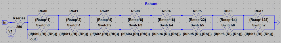
This thread makes a excel sheet available that is intended to calculate the binary values needed to create a resistor ladder network emulating a logarithmic potentiometer with a fixed series element.
Edit: Updated version in post #2 (below).
Edit: Do not download these(old) files, download the files from post #2.
Edit: Updated version in post #2 (below).
Edit: Do not download these(old) files, download the files from post #2.
Attachments
-
Digital Shunt Potentiometer.zip509.2 KB · Views: 90
-
 DigitalShuntPotentiometer.png113.4 KB · Views: 382
 -
 DigitalShuntPotentiometer(Excel detail).png44.9 KB · Views: 391
 -
 DigitalShuntPotentiometer(Ladder network).png23.9 KB · Views: 325
 -
 DigitalShuntPotentiometer(Use case).png33.3 KB · Views: 337
 -
DigitalShuntPotentiometer.pdf279.5 KB · Views: 92
Last edited:
Updated version of the files above, sorry for that 🙂 All files (and more) are included in the .zip-file.
Attachments


Thank
No thanks, it is a spread-sheet that I developed for my own use and it seemed to me that it may be usefull to other people also,... so why not post it 🙂
Be shure to download the one from the second post.
are you saying that Rseries does not vary and that the volume adjustment is achieved by varying Rshunt?
are you saying that Rseries does not vary and that the volume adjustment is achieved by varying Rshunt?
Yes, I am 🙂
The benefit is, no added distortion at maximum volume (and most listening levels). The price to pay is a slightly higher noice, but if the series elemt is kept of a low resistance then this noise is neglectabel.
In the case that the maximum voltage is 2V (on the input) and the series element is 200 ohms then the maximum current, at zero volume, is 20mA. This is easily handled by most (if not all) opamps (or other buffers) so having a series element of 100 ohm is no problem, and the added noise is extremely low. At maximum volume the series element has a high value so the current load on the opamp is neglectable (when the shunt element is 1k it will be 2mA).
At 100 ohms it is 0.20663493 uV at 1kHz or -133.695925 dBV. http://www.sengpielaudio.com/calculator-noise.htm
Last edited:
A 200r series element is going to give an input impedance that varies with volume level from a few kohms to 200r.
That is not a reasonable load for any normal line driving stage.
Most can cope with driving 10k to 100k.
Some will cope with driving 2k to 10k.
Very few will be able to drive << 2k.
200r is nonsense. 100r is even worse.
That is not a reasonable load for any normal line driving stage.
Most can cope with driving 10k to 100k.
Some will cope with driving 2k to 10k.
Very few will be able to drive << 2k.
200r is nonsense. 100r is even worse.
A 200r series element is going to give an input impedance that varies with volume level from a few kohms to 200r.
That is not a reasonable load for any normal line driving stage.
Most can cope with driving 10k to 100k.
Some will cope with driving 2k to 10k.
Very few will be able to drive << 2k.
200r is nonsense. 100r is even worse.
This is not fair.
First of all it in the diagrams shown in post 1 I show buffers that should be used to drive the low impedance.
Second even D Self is using 1K resistors in his preamp.
Third it is just a quick example. And yes you are right most preamps will not drive such a low load, but who ever told advice to do that (load a preamp with 100 ohm)?
Fourth this was explained in the attached PDF (did you check that out).
Fifth, if you like to use higher values, then just do that, I am not saying that you must use extreme low values.
Sixth I am not providing a preamp/linestage/volumebuffer etc design just a spread-sheet that may help designing digital controlled shunt potentiometers (low or/and high values0
Anyway, the extreme low impedance is only applied at zero volume, and not at listening levels (even low ones). So what is your point.
Most of the time a 10K potentiometer (lets say at 90%) will add a series resistance of 1K (more or less) adding more noise to the signal than the low ohmic version using buffers.
Last edited:
you said 100r or 200r. I did not invent those values.
You said it without giving any warning to potential users who may decide to adopt your attenuator.
let's look at a wider range of input impedance rather than just at
-0.1dB, Rseries = 200r, Rshunt = ~16k, Rin = ~16k2
-1dB, Rseries = 200r, Rshunt = ~1k7, Rin ~1k9
-3dB, Rseries = 200r, Rshunt = ~470r, Rin ~670r
-6dB, Rseries = 200r, Rshunt = ~200r, Rin ~400r
-10dB, Rseries = 200r, Rshunt = ~91r, Rin ~291r
-20dB, Rseries = 200r, Rshunt = ~22r, Rin ~222r
-30dB, Rseries = 200r, Rshunt = ~7r, Rin ~207r
-40dB, Rseries = 200r, Rshunt = ~2r, Rin ~202r
There's my point.
and using 100r is even worse.
Using Rseries=2k, would make a usable attenuator that could be driven by many Buffers.
You said it without giving any warning to potential users who may decide to adopt your attenuator.
let's look at a wider range of input impedance rather than just at
Anyway, the extreme low impedance is only applied at zero volume
-0.1dB, Rseries = 200r, Rshunt = ~16k, Rin = ~16k2
-1dB, Rseries = 200r, Rshunt = ~1k7, Rin ~1k9
-3dB, Rseries = 200r, Rshunt = ~470r, Rin ~670r
-6dB, Rseries = 200r, Rshunt = ~200r, Rin ~400r
-10dB, Rseries = 200r, Rshunt = ~91r, Rin ~291r
-20dB, Rseries = 200r, Rshunt = ~22r, Rin ~222r
-30dB, Rseries = 200r, Rshunt = ~7r, Rin ~207r
-40dB, Rseries = 200r, Rshunt = ~2r, Rin ~202r
There's my point.
and using 100r is even worse.
Using Rseries=2k, would make a usable attenuator that could be driven by many Buffers.
Last edited:
10k at the input to a power amp is roughly equivalent to an Ein of 12nV/rootHertz........................
Most of the time a 10K potentiometer (lets say at 90%) will add a series resistance of 1K (more or less) adding more noise to the signal than the low ohmic version using buffers.
That gives an output noise of ~ 12*141*28 ~ 0.04mVac of noise voltage and equates to ~ -114dB ref 50W into 8ohms.
A 100k vol pot with Rseries =10k and Rshunt = 90k (vol pot @ ~-1dB) is a non issue for most power amplifiers.
A 10k vol pot is a non issue, noise wise, for all power amplifiers.
2k noise is so low, we will hardly be able to measure the added noise at the output of the subsequent power amplifier.
you said 100r or 200r. I did not invent those values.
You said it without giving any warning to potential users who may decide to adopt your attenuator.
let's look at a wider range of input impedance rather than just at
-0.1dB, Rseries = 200r, Rshunt = ~16k, Rin = ~16k2
-1dB, Rseries = 200r, Rshunt = ~1k7, Rin ~1k9
-3dB, Rseries = 200r, Rshunt = ~470r, Rin ~670r
-6dB, Rseries = 200r, Rshunt = ~200r, Rin ~400r
-10dB, Rseries = 200r, Rshunt = ~91r, Rin ~291r
-20dB, Rseries = 200r, Rshunt = ~22r, Rin ~222r
-30dB, Rseries = 200r, Rshunt = ~7r, Rin ~207r
-40dB, Rseries = 200r, Rshunt = ~2r, Rin ~202r
There's my point.
and using 100r is even worse.
Using Rseries=2k, would make a usable attenuator that could be driven by many Buffers.
And my point is, this is not the point. I am only providing a excel-sheet to calculate values for digital-controled-shunt-only potentiometers. And I was advising (for the given samples) to use a separete buffer amp (and not to apply it to the amplifier input or pre-amp output directly) where was I not clear?
Your figures are what they are (true 🙂) and at normal levels -6dB the impedance is (as you show) 400 ohm (as I said, this will work with most opamp (or other) buffers [see the PDF]).
Last edited:
10k at the input to a power amp is roughly equivalent to an Ein of 12nV/rootHertz.
That gives an output noise of ~ 12*141*28 ~ 0.04mVac of noise voltage and equates to ~ -114dB ref 50W into 8ohms.
A 100k vol pot with Rseries =10k and Rshunt = 90k (vol pot @ ~-1dB) is a non issue for most power amplifiers.
A 10k vol pot is a non issue, noise wise, for all power amplifiers.
2k noise is so low, we will hardly be able to measure the added noise at the output of the subsequent power amplifier.
This all being true (and I am not arguing that) when the 10K is at -6dB then the series resistance is 5K, and that is a larger noise source than 200 ohms. You can do what ever you want this is not my concern and I never advised to use 200 ohms (it was just an example).
Again, I am not designing a pre-amp here, I am just providing a tool (spread-sheet) to calculate step values for digital controlled shunt potentiometers. If you do not like it, do not use it.
Please do not confuse the purpose of the thread, if you want to design and discuss design issues for a pre-amp, investigating the positives and negatives of shunt-only potentiomers you should open a new thread for that purpose.
There are many who adopt ideas from the Forum, but do not know how they work.
A fair warning to them would have been useful.
Noise whether it is due to an added Rseries of 100r, or 10k, is not an issue for Power amplifiers with S/N ratio of around 100dB to 120dB.
A fair warning to them would have been useful.
Noise whether it is due to an added Rseries of 100r, or 10k, is not an issue for Power amplifiers with S/N ratio of around 100dB to 120dB.
There are many who adopt ideas from the Forum, but do not know how they work.
A fair warning to them would have been useful.
Noise whether it is due to an added Rseries of 100r, or 10k, is not an issue for Power amplifiers with S/N ratio of around 100dB to 120dB.
Maybe, but now that has been done. It was never said that this was a part of an power amplifier (or any thing else). Its just what it is, a spread-sheet to calculate resistor stap values for digital controlled shunt potentiomets.
I for one am grateful for the provided spread sheet and explanations.
Cool 🙂 if you need more explanations or can think of a improvement, just let me know. Have fun with it.
If you keep the Rseries resistors below about 1.5 k Ohms, you can still get outstanding noise performance with this design. Good opamps like a 5534 or AD797 will easily cope with that type of load. On my Symphony preamp, I use a 5 k pot, so the worst case input R seen by the buffer is 2.5 k Ohms. The buffer feeds the power amp. It's the quietest preamp I have built. You can see the schema on my website and the write up on the noise calculations and gain structure.
If you keep the Rseries resistors below about 1.5 k Ohms, you can still get outstanding noise performance with this design. Good opamps like a 5534 or AD797 will easily cope with that type of load. On my Symphony preamp, I use a 5 k pot, so the worst case input R seen by the buffer is 2.5 k Ohms. The buffer feeds the power amp. It's the quietest preamp I have built. You can see the schema on my website and the write up on the noise calculations and gain structure.
Yes, in my (current) design I am using 2xLME49710 (balanced) and 2x500 Ohm in series, the opamp's are offset into class A using current sources of 5mA while the maximum output voltage (at the opamp's) is 2V (this works great).
Last edited:
- Status
- Not open for further replies.
- Home
- Source & Line
- Analog Line Level
- Shunt Potentiometer Calculator Excel-sheet