Recommend a basic oscilloscope
There are some portable scopes available, within reach. Any of these recommended?
10 Best Portable Oscilloscope Handpicked for You in 2021 - Best Review Geek
Anyone use AUKUYEE Updated 2.4" TFT Digital Oscilloscope Kit with BNC-Clip Cable Probe Q15001O (Assembled Finished Machine)
Brand: AUKUYEE
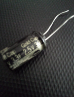
Can you get me a picture of that 3F Capacitor, Please.. do not see that one in your Picture from here..
Also make a readout with a scope as long it's on the bench table.. it helps a lot to reduce later disappointments when all is finished and it doesn't work as expected anymore..
Thanks
There are some portable scopes available, within reach. Any of these recommended?
10 Best Portable Oscilloscope Handpicked for You in 2021 - Best Review Geek
Anyone use AUKUYEE Updated 2.4" TFT Digital Oscilloscope Kit with BNC-Clip Cable Probe Q15001O (Assembled Finished Machine)
Brand: AUKUYEE
Last edited:
BasicHiFi1 - you haven't answered any questions about your 3F capacitor.
If you won't post a photo at least tell us what the writing on it actually says?
If you won't post a photo at least tell us what the writing on it actually says?
The SuperCapacitor
Oh sorry, I took the photo some time ago... didn't post it: here it is. The capacitor is removed, and it was getting too hot. I am looking through the threads for a good class A circuit to build next. No more fake circuits from You Tube.
Here are the measurements: C1: 50V, 1 uF, C2: 2V, 3F
Power Off
C1: 0.199V
C2: 0.966V
Power On
C1: 0.5V
C2: 4.1V rising to 5.8V in about two minutes
As you recall replaced C2 with 47 uF and it got very hot.
Attachments
It’s no surprise that it’s running hot with a 2.5 volt cap. Even if it were biased *properly* it would have 4.5 volts on it with a 9 volt supply. If you ran it on higher voltage, you might have confetti all over the room, and a capacitor can embedded in the ceiling.
And if it were hooked up like post #5 (which is incorrect), the leakage current thru the cap is what is actually providing the bias path *through* the speaker. Output power would be very low, and clipping probably asymmetrical. Hence, the distortion.
And if it were hooked up like post #5 (which is incorrect), the leakage current thru the cap is what is actually providing the bias path *through* the speaker. Output power would be very low, and clipping probably asymmetrical. Hence, the distortion.
Current amplifier circuit. Current meaning latest.
Right. Thank for saving my ceiling.
The next step is to get a good circuit diagram. Here is one I quickly drew up using an online free tool which is really the best I have come across so far. The values are all wrong but you get the idea. I will input the values and re-post. I lost the circuit - not saved as it was a trial - not logged in.
Attachments

The scheme is wrong. Either change the collector and emitter, or switch the bias to the collector. #2,5,21,26,46 ?????? ????????? ???????? ?? ????????????
A special transformer is required (for audio). Упрощённый расчёт выходного трансформатора однотактного SE усилителя. - YouTube
Do you read what forum members write to you?
A special transformer is required (for audio). Упрощённый расчёт выходного трансформатора однотактного SE усилителя. - YouTube
Do you read what forum members write to you?
Last edited:
Final circuit diagram with components listed. Vcc is 9V, transistor is a TIP41. Transformer is a 220 V / 9V from a PC speaker power unit.
tip41a tip42a pinout - theoryCIRCUIT - Do It Yourself Electronics Projects
tip41a tip42a pinout - theoryCIRCUIT - Do It Yourself Electronics Projects
Attachments

The scheme is wrong. Either change the collector and emitter, or switch the bias to the collector. #2,5,21,26,46 ?????? ????????? ???????? ?? ????????????
A special transformer is required (for audio). Упрощённый расчёт выходного трансформатора однотактного SE усилителя. - YouTube
Do you read what forum members write to you?
I will look for a standard approved circuit and follow that.
OK this is good. Modify and use I guess. I need a load resistor and the speaker to be in parallel with the transistor and load resistor. OK.
https://i.pinimg.com/564x/73/e9/9b/73e99b15b1243fbfd61cc33f604ef400.jpg
There are the John Audio Tech designs but these use different transistors.
This one uses a Darlington transistor
Build this Amazingly simple class A amplifier - YouTube
This one uses the IRF244
Class A MOSFET amplifier using one transistor - with schematic - YouTube
Last edited:
Redesign using common emitter amplifier scheme
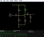
Back to the drawing board. The simple one-transistor amplifier used as examples will not suit our purposes here. The next step up is the 'common emitter amplifier' - many examples from the more experienced lets say electronics experts online.
The Falstad circuit example seems to be quite standard, so I will use that as a basis. I already have the TIP41 transistor at hand, so here it is.
Attachments


I want to use a 9V power supply, but that drops the signal into negative territory. How do I correct this? I tried changing the bias resistor but to no avail.
The other one is an emitter-follower setup which uses only 5V.
The other one is an emitter-follower setup which uses only 5V.
Attachments

Last edited:
Change the 110k resistor. It’s going to take a fairly large change. Sweep the value down, and find out what puts about 5 volts at the collector.
Say you have 9V supply, you want the queiscent collector voltage to be about 5V.
Decide the collector current you want, lets for the sake of an example say 10mA.
Then the collector resistor must be 400 ohms = (9-5)/0.01
For a gain of about 10 choose emitter resistor of 40 ohms. In practice that's 390 ohms and 39 ohms.
Thus the emitter voltage will be about 0.4V (0.01 * 40)
Thus the base voltage should be Vbe+0.4 or about 1V (Vbe is around 0.6 to 0.7V in
typical setups). So the base bias resistors could be 10k and 82k, dividing 9V down to about
1V. Tune these to bring the collector voltage to 5V.
The choice of collector current depends on the load.
I suggest you learn the basics so you understand and can answer yourself, which is the proper way to go, and in the long run, the best.
Otherwise you will need to post a question and wait for answers (which will often trigger more questions on and on) for EVERY single step in a LONG road.
Notice for the last 2 years you are bogged down to single transistor circuits, and even worse, apparently you learnt nothing, since you are like on the first day.
As a side note, you would have learned to solder like a Pro, if you had even tried.
Feeding you teaspoons of pap in the mouth one by like a Baby is not the way to learn.
Even Babies learn to grab a plastic spoon and feed themselves (sort of) in 2 years or more.
By now you should AT LEAST be able to design and build a working single transistor amp ... but you are not.
You could (should) have learnt a lot in 2 years.
I concur with JMFahey. Even if you build a transistor stage along the lines Mark T suggests, it won't drive an 8 ohm speaker with any significant power without changing the resistors substantially (much lower) as has been pointed out in previous answers.
You seem stuck on the basics.
Not even aware that applying 4V to a 2.5V capacitor might be a bad thing!
And it might be much better if you do find a decent electronics course or book. Before you get disappointing results or damage something.
You seem stuck on the basics.
Not even aware that applying 4V to a 2.5V capacitor might be a bad thing!
And it might be much better if you do find a decent electronics course or book. Before you get disappointing results or damage something.
Last edited:
Say you have 9V supply, you want the queiscent collector voltage to be about 5V.
....
The choice of collector current depends on the load.
Thanks Mark. The above values do not really give a proper amplified output in the Falstad Circuit Sim. Are you saying to try it in the simulator or with actual components?
Short answer(s):
1) in this very simple case, simulator or breadboarding will give exact same results, because this is all basic, well known, well documented stuff.
Here Models work perfect.
Simulators start to fall apart when trying circuits and components well beyond "normal" use, where usually unimportant (and so not incorporated into generic models) become important.
Say working well above Ft, or at current beyond what´s shown in datasheet, or mounted on an improper heatsink which lets parts overheat, etc. , that´s why nobody goes straight from simulator to production, there will always be some prototypes and final tweaking involved.
But that is not your case.
2) even with the best Simulator in the World ... you have to "feed" it 😎
You provide it with some values and it will faithfully tell you how that will work, output lots of data, graphs, distortion, whatever ... but you must feed it those values first!!!!
Simulators are impressive tools, but not Magic, at least they don´t read minds.
Star Trek Computers used no keyboards for input, nor monitors for output, you *asked* them something and they answered:
Star Trek Voice First Computer - YouTube
but real ones do not work that way, neither Simulators do, you have to do your part, or else.
Although Alexa is trying to go that way 😉
3) you might throw some values at random at it and pray ... fat chance of getting anything even remotely useful that way.
Probabilities are same as going on a Safari in Africa, blindfolded, and shooting now and then trying to get a Lion or something.
You should be able to sketch a nearly working plan on a napkin. Many of the great designs started that way.
You do not seem to have this aptitude. You are trying to plan a 20 story building out of one board supported on just one end.
(Do we know 5-1/4" floppy disks, and why that size? The cocktail napkins where Al Shugart used to drink.)
You do not seem to have this aptitude. You are trying to plan a 20 story building out of one board supported on just one end.
(Do we know 5-1/4" floppy disks, and why that size? The cocktail napkins where Al Shugart used to drink.)
BasicHifi1: if you are going to progress, why not start with the collector load you are likely to need (say 8 or 10 ohms to match the speaker) and then follow Mark T's maths to calculate the remaining three resistors.
Then plug that into your simulator and see if you get a signal out.
Simulators can be as useful as a "sketch on a napkin" even for simple circuits. But if you can't grasp the fundamentals (ohm's law) it's going to be an uphill struggle.
You actually don't need a simulator for such a simple circuit, but a calculator is handy.
- Home
- Amplifiers
- Solid State
- Simple Class A Amplifier Project