If you haven't read through them yet, I think you'll probably find great reassurance in the QM measured results of other diyAudio members:
thread: Quasimodo results (ONLY)
looking at the photos in post #1800, I'd suggest either a 15R or a 12R component for the snubbing resistor Rs. Whichever is in stock on the day you're buying.
thread: Quasimodo results (ONLY)
looking at the photos in post #1800, I'd suggest either a 15R or a 12R component for the snubbing resistor Rs. Whichever is in stock on the day you're buying.
Just a parenthetical -- I just re-read the PDF (hard to believe it's been 7 years!). Caught the reference to the Crown IC-150. That's the roomiest preamplifier I own.
Wow, I didn't know that thread existed--very helpful.If you haven't read through them yet, I think you'll probably find great reassurance in the QM measured results of other diyAudio members:
thread: Quasimodo results (ONLY)
looking at the photos in post #1800, I'd suggest either a 15R or a 12R component for the snubbing resistor Rs. Whichever is in stock on the day you're buying.
And thanks MJ for this excellent project you've provided for DIY'ers of all skill level!
I have some more transformers to measure and I will share my results in the results thread.
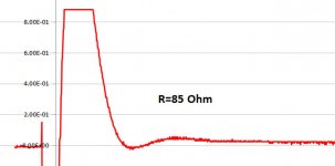
So here's some data for the stock transformer in a Hafler DH-500. This is a single-secondary, CT transformer which gives +/- 90 VDC rails. The results give a higher resistor than for the Hafler XL-280 transformer.
My guess is that R between 68 and 56 Ohm gives the desired result. At this resistance the 2nd swing is completely obliterated. In the detail view it can be seen than R lower than 56 only produces more quenching of the first swing, which as I understand it is not the goal.
Is it agreed that ~60 Ohm is the right value?
Thanks,
Ron
Attachments


So here's some data for the stock transformer in a Hafler DH-500.
But can you hear the switching transient? Or can you demonstrate that it is present on the output?
Mbe run a test with 1kHz or 10kHz signals into a dummy load and look for the intermodulation products.
Just curious.
But can you hear the switching transient? Or can you demonstrate that it is present on the output?
Mbe run a test with 1kHz or 10kHz signals into a dummy load and look for the intermodulation products.
Just curious.
I've not yet installed a single snubber, I'm only now learning the component values I need. I have more than one Hafler DH-200 so I may add a snubber to one of two of them that are otherwise indistinguishable (sonically), then after snubbing compare them again.
Regarding measurements, I have the means (equipment), but I have yet to set it up to take these measurements. It will be a bit of a learning curve the first time.
But I intend to investigate this, and other such things. I think there exists data to support that a quiet power supply produces less distortion than a noisier one, but I have no data that I myself have collected.

I think there exists data to support that a quiet power supply produces less distortion than a noisier one, but I have no data that I myself have collected.
If you think about it, an amplifier is just a modulator for the power supply.
So a clean and quiet PSU can only be beneficial. 😀
I ordered resistors for 62 Ohm--I think it's close enough for hand grenades, atoms bombs, and snubbers.🙂Critical damping is when the second lumpity bumpity juuuuuust goes flatline, as indicated by the yellow arrowhead in QM Figure 10. You want to duplicate the RED trace. Be brave, use your best judgement.
_
So I hooked a transformer from one of my Hafler DH-200's to the quasimodo rig and obtained these results. I have several DH-200's but I've only measured the one for now. I think they won't vary much from unit to unit, but I will post my results either way, once I do the measurements. For now I've ordered 39 Ohm resistors for "snubbering" these amps.
Attachments

@Rinman
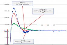
thanks sa lot for sharing! I am learning the optimum judgement at the moment, so please let me understand why for you the red curve 39Ohm and not the green curve 23Ohm is the optimum. In my judgement the red curve still shows some (small!) ringing which the green one does not...
Thanks and Regards,
Winfried
I am also only learning. But let me post the individual curves to see if you still feel the same way. First let me explain that I consider "properly snubbed" to be indicated by the flattening of the 2nd swing at the point where it originally dips below the zero line, as indicated in Figure 10 of the original Quasimodo and document, and as is reprinted in post 1807 by MJ himself. In his example the first swing remains intact, though greatly dampened, but it is the eradication of the 2nd dip that is used as the criteria for zeta=1. I have marked up the attached scans with this in mind.@Rinman
thanks sa lot for sharing! I am learning the optimum judgement at the moment, so please let me understand why for you the red curve 39Ohm and not the green curve 23Ohm is the optimum. In my judgement the red curve still shows some (small!) ringing which the green one does not...
Thanks and Regards,
Winfried
Ron
Attachments


Hi Ron,
thanks for your prompt answer! The individual screenshots help clarify your point more obviously! I'm going to do some measurements soon and will do the analysis be screenshots as well, instead of "just" using the CRT trace itself.
Thanks,
Winfried
thanks for your prompt answer! The individual screenshots help clarify your point more obviously! I'm going to do some measurements soon and will do the analysis be screenshots as well, instead of "just" using the CRT trace itself.
Thanks,
Winfried
Hard to find optimum case with R-Core from ZeroZone
Hello Folks,
after having done many successful snubber optimization measurements over recent weeks, always leading to textbook optimums, I have now come across transformers with puzzling ringing behavior, despite these transformers working flawlessly in their applications so far. The behavior is only seen with ZeroZone R-Cores (so far), Audiophone R-Cores behave as expected. Please see the screenshots below and my only question to the knowledgeable Transformer and Quasimodo experts is: Which R-value do I take for the transformer?
Thanks a lot for your kind advice!
Winfried
PS: Just to make sure: The test set up is identical to the "well working" cases, also the procedure followed is identical!
PPS: If this is the wrong thread to ask my question, please advise where I should post this. Thanks!
Attachments
-
 ZZ01 2VDivn 10µsDivn R open.png69.7 KB · Views: 442
 -
 ZZ02 1VDivn 5µsDivn R 500Ohm.png21.6 KB · Views: 227
 -
 ZZ04 1VDivn 5µsDivn R 100Ohm.png20.4 KB · Views: 223
 -
 ZZ05 1VDivn 5µsDivn R 80Ohm.png20.5 KB · Views: 214
 -
 ZZ06 1VDivn 5µsDivn R 60Ohm.png20.2 KB · Views: 216
 -
 ZZ08 1VDivn 5µsDivn R 40Ohm.png20.1 KB · Views: 218
Last edited:
 The above post has been moved here from the results thread.
Thank you Moderator! The author of #1814 was concerned (correctly!) that he put it in the wrong place.
Thanks for moving my post to the right location!
I hope someone can make sense of the measurements and can give advice on how to handle the strange transformer response. My suspicion is that the measured transformer somehow may have two resonances, only one of which being compensateable by a snubber... The question "where is the optimum" in this case remains.
Thanks and Regards,
Winfried
I have a total of 4 Hafler DH-200. Their stock EI core transformers have a single secondary with a CT. I earlier took Quasimodo measurements on one of these transformers, on only one of the two leads against the CT. I received a result of 39 Ω. I assumed the 2nd lead against CT would render the same result. Well today I took measurements on one of my other DH-200 transformers, but this time I measured both secondary leads against the CT--I obtained different results. Not hugely different, but different outside the range of error even given the subjective nature of choosing "flat" for zeta = 1. I then measured yet another one of these transformers and obtained a very similar result. So I will identify these transformers by the S/N on the amp. Again, these are all Hafler DH-200 amps with their stock EI core transformers.
But if someone is looking to these resutls, but doesn't have the means to measure for optimal snubbing themselves, I guess a resistor of value 35 should be OK for both pairs. Would this be good advice?
Thanks,
Ron
- S/N = 3211064
- 2ndary 1a to CT: 28 Ω
- 2ndary 1b to CT: 40 Ω
- S/N = 3938020
- 2ndary 1a to CT: 28 Ω
- 2ndary 1b to CT: 42 Ω
- S/N = unknown (tag is missing) (This is the one measured earlier)
- 2ndary 1a to CT: 39 Ω
But if someone is looking to these resutls, but doesn't have the means to measure for optimal snubbing themselves, I guess a resistor of value 35 should be OK for both pairs. Would this be good advice?
Thanks,
Ron
I have encountered this same difference in results with other EI core CT transformers, although the numbers were not quite as far apart as yours are. I assume that one secondary is physically wound over top of the other, resulting in a slightly different inductance for each one. I installed different values of snubber resistors for each winding as you suggest.
I also agree that about 35 ohms would be an acceptable compromise value if you are unable to directly measure a DH-200 transformer yourself.
Take care,
Doug
I also agree that about 35 ohms would be an acceptable compromise value if you are unable to directly measure a DH-200 transformer yourself.
Take care,
Doug
... and my only question to the knowledgeable Transformer and Quasimodo experts is: Which R-value do I take for the transformer?
Suppose you had to choose a value all by yourself: which one looks best (or which one looks least bad), to you? and why?
- Home
- Amplifiers
- Power Supplies
- Simple, no-math transformer snubber using Quasimodo test-jig