I got the proto of the s.e. trafo with multi tap
5 kohm, 43% and 20% UL
5 ohm single secondary
around 20H
primary wire 0,28 mm diam - Rdc 140 ohm
max Ia around 200mA
Pmax around 10 watt, column 40x45,
M3 - 0,3 mm. o.g.
4,4 kg


This is not available.
To play in the real world not in virtual
Testing some circuit.
Unfortunately I have to service now my Sofia ( some hard problem) then I can test the tube that will play in the circuit
proposed
Walter
5 kohm, 43% and 20% UL
5 ohm single secondary
around 20H
primary wire 0,28 mm diam - Rdc 140 ohm
max Ia around 200mA
Pmax around 10 watt, column 40x45,
M3 - 0,3 mm. o.g.
4,4 kg
This is not available.
To play in the real world not in virtual
Testing some circuit.
Unfortunately I have to service now my Sofia ( some hard problem) then I can test the tube that will play in the circuit
proposed
Walter

@waltube an ultralinear transformer is offtopic on this thread, and I will not fall for the constant provocation of your real world vs others simulations, but I hope you will use that 20% tap together with the Schade feedback I suggested you on the Italian forum and that you said that doesn’t work because no one of the great designers of hi-fi history ever implemented it.
You don’t understand the reasonan ultralinear transformer is offtopic
This trafo can be configured for different circuit included the one proposed here
And not mistified
I wrote that I can’t understand why the moltitude of brand didn’t use the Schade configuration
Not that can’t work!!!!!!!
This iron will clear to me if it is good or not with proper real tests
With calm and time
I have all stuff to run good!
Ciao
Walter
Walter, you need to read the full thread, not the first post only.This trafo can be configured for different circuit included the one proposed here
On LTSpice there was an optimum with Vg2-k constant, that I haven't found when I built it.
It works best when Vg2 is fixed: in pentode mode.
Do not exceed 10W of idle dissipation on the TO220 pmosfet source follower.
If that driver can swing enough, with that trafo you can use an EL34 with around 20% a-g1 feedback (150k + 150k + 68k).
You should get a DF around 4 with that transformer (what is secondary Rdc?).
10% is fine as well with EL34, targeting less power, less linearity but an easier job for the driver.
The ones not only oneThis trafo can be configured for different circuit included the one proposed here
my error on post
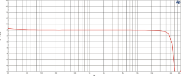
The first test on trafo, just signal coming fromAP Sys2
6 volt on primary, Zs = 50 and 600 ohm
Secondary terminated on 8 ohm
ratio prim/sec = 35
No Dc at this moment.
Checked the voltage at the tap with 6 Vin
43 % = 2,95 volt (theory 2,58 volt)
20 % = 1,20 volt ( theory 1,20 volt)
Good response, little indecision but it is a proto
Follow in next days tha test in reverse mode up to around 10 Wrms
Blu line is Zs= 20 ohm
Green line is Zs = 600 ohm
I am preparing a test circuit, probably using an ECC88 (but also 6H30, very linear), in Srpp; this to have a good swing in input at reasonable low THD
 Thread split from here - https://www.diyaudio.com/community/threads/single-ended-the-pentode-retaliation.373257/
The first tests
Triode
Vdc = 317 v
Ia = 66 mA
Vk = 26,5 volt
Rk = 390 ohm
Vin =13 Vrms
VPrimary = 84 Vrms measured with differential probe
Gain of the stage = 6,5
Vsec = 2,45
Raratio = 35
Freq. response

Some indecision at around 100 kHz
FFT

Phase

Without any gain stage at the moment, only the 88 in triode mode driving by Ap Sys2
Walter
Triode
Vdc = 317 v
Ia = 66 mA
Vk = 26,5 volt
Rk = 390 ohm
Vin =13 Vrms
VPrimary = 84 Vrms measured with differential probe
Gain of the stage = 6,5
Vsec = 2,45
Raratio = 35
Freq. response
Some indecision at around 100 kHz
FFT
Phase
Without any gain stage at the moment, only the 88 in triode mode driving by Ap Sys2
Walter
Attachments

This is the start test set, First step.
This is the basic circuit with the option to set the Schade circuit
The X and Y are the connection point for Schade, plus P for Pentode then UL for 20 and 43%

This is the desk
There are three trafos for tests, two custom ( with UL at 20 and 43%) and one Hammond 1627SE, UL at 43%; I have also a beautiful Kikusui power supply 0-350 vdc- 100 ma, very fine to have a clean voltages ( the old one I had was dead! was a previous model)

The tube is KT88, driven directly form AP
There are some limitation on max signal but enough for the firsts test. Mainly for sweep on freq. response.
Next step is to implement a linear ( most possible) drive circuit to reach a real s.e. stage
The first test was done in triode mode with the trafo in the photo on previous post.
Some checks but it is not important for the test
Then I check the pentode mode and it is not very interesting. But I found the gain of the KT88
Signal is 1 kHz
Vin = 1,8 v
Vout = 2 volt / 8 ohm
Thd = 2,4 %
Vprimary = 70 vac (gain = 39)
ratio = 35
---------------------------------------------------------------------------------
Then in Schade
Vdc = 340 v
Ia = 80 mA
Vin = 9.1 v
Vout = 2 v - 8 ohm
1,7 v - 4 ohm
Thd= 0,53 %
Vprim = 73 ( gain = 8 )
Vsec = 2 volt
FB = 13,7 dB > pentode
The freq. resp. at 1,2 volt , 8 - 4 ohm ( due the signal limit of AP for swing)
Some indecision at more than 60kHz but it is good; around 1.5 dB of difference between 8 and 4 ohm, a reasonable low Zout. ( at the end of the tests a DF will be calculate)

The FFt at 2 Vout ( 9,1 Vin). the III is too high and only 6dB of difference, also IV

--------------------------------------------------------------------------------------------------------------------
UL 43%
Vout = 2 V 8 ohm
1,71v 4 ohm
Thd = 1,2 %
The frq response, 4/8 ohm quite similar to previous but better on low end.

The FFT, 2 Vout, II high but the III is around 15 dB lower than previous , the IV is much lower.

------------------------------------------------------------------------------------------------------------------------------------------------
UL 20%
Vout = 2
Thd = 1,41%
Vout = 2 v su 8 ohm
1,77 su 4 ohm
Freq. resp, quite similar to before.

The FFT

-------------------------------------------------------------------------------------------------------------------------------
Just to check with another trafo, I used the Hammond
The 1627 has 2500 and UL at 43%; I connect the 8 ohm to the 4 ohm tap just to reach a good value of Z. In this case the ratio is 27 and the reflected is 5200 ohm comparable with the previous trafo and high enough for the tests
Hammod and Schade
Freq. resp, only 8 ohm, it is good enough

The FFT; Thd is 0,28% at 2 vout. The III is high as for the previous test; the difference from IInd is 6 dB!!

----------------------------------------------------------------------------------------------------------------------------
Hammond 43%
Freq. response, 8 ohm
little bit better: the difference with 4 ohm is around 1,5 dB as the previous tests

The FFT
2 vout with 1,5% thd; the III at -68 db and 30 dB lower than IInd ; the difference with Schade on IIIrd is 10 dB lower

So the first impression is confirmed. For me
And it is evident that the quality of the trafo is basilary.
These are the firsts test; other with changes in the schematic as the proposed with the insertion of sand will arrive.
And one more trafo will be involevd
Walter
This is the basic circuit with the option to set the Schade circuit
The X and Y are the connection point for Schade, plus P for Pentode then UL for 20 and 43%
This is the desk
There are three trafos for tests, two custom ( with UL at 20 and 43%) and one Hammond 1627SE, UL at 43%; I have also a beautiful Kikusui power supply 0-350 vdc- 100 ma, very fine to have a clean voltages ( the old one I had was dead! was a previous model)
The tube is KT88, driven directly form AP
There are some limitation on max signal but enough for the firsts test. Mainly for sweep on freq. response.
Next step is to implement a linear ( most possible) drive circuit to reach a real s.e. stage
The first test was done in triode mode with the trafo in the photo on previous post.
Some checks but it is not important for the test
Then I check the pentode mode and it is not very interesting. But I found the gain of the KT88
Signal is 1 kHz
Vin = 1,8 v
Vout = 2 volt / 8 ohm
Thd = 2,4 %
Vprimary = 70 vac (gain = 39)
ratio = 35
---------------------------------------------------------------------------------
Then in Schade
Vdc = 340 v
Ia = 80 mA
Vin = 9.1 v
Vout = 2 v - 8 ohm
1,7 v - 4 ohm
Thd= 0,53 %
Vprim = 73 ( gain = 8 )
Vsec = 2 volt
FB = 13,7 dB > pentode
The freq. resp. at 1,2 volt , 8 - 4 ohm ( due the signal limit of AP for swing)
Some indecision at more than 60kHz but it is good; around 1.5 dB of difference between 8 and 4 ohm, a reasonable low Zout. ( at the end of the tests a DF will be calculate)
The FFt at 2 Vout ( 9,1 Vin). the III is too high and only 6dB of difference, also IV
--------------------------------------------------------------------------------------------------------------------
UL 43%
Vout = 2 V 8 ohm
1,71v 4 ohm
Thd = 1,2 %
The frq response, 4/8 ohm quite similar to previous but better on low end.
The FFT, 2 Vout, II high but the III is around 15 dB lower than previous , the IV is much lower.
------------------------------------------------------------------------------------------------------------------------------------------------
UL 20%
Vout = 2
Thd = 1,41%
Vout = 2 v su 8 ohm
1,77 su 4 ohm
Freq. resp, quite similar to before.
The FFT
-------------------------------------------------------------------------------------------------------------------------------
Just to check with another trafo, I used the Hammond
The 1627 has 2500 and UL at 43%; I connect the 8 ohm to the 4 ohm tap just to reach a good value of Z. In this case the ratio is 27 and the reflected is 5200 ohm comparable with the previous trafo and high enough for the tests
Hammod and Schade
Freq. resp, only 8 ohm, it is good enough
The FFT; Thd is 0,28% at 2 vout. The III is high as for the previous test; the difference from IInd is 6 dB!!
----------------------------------------------------------------------------------------------------------------------------
Hammond 43%
Freq. response, 8 ohm
little bit better: the difference with 4 ohm is around 1,5 dB as the previous tests
The FFT
2 vout with 1,5% thd; the III at -68 db and 30 dB lower than IInd ; the difference with Schade on IIIrd is 10 dB lower
So the first impression is confirmed. For me
And it is evident that the quality of the trafo is basilary.
These are the firsts test; other with changes in the schematic as the proposed with the insertion of sand will arrive.
And one more trafo will be involevd
Walter
Attachments


Step Two
This is a complete circuit where I will test the different config.

I used the 6H30 and 6922 fot the linearity that is good.
Some test on them, only input circuit
6922 / PCC88 Tungsram nos
Ia = 10 mA ( 1,5 watt/ anode, hard job)
Gain around 22
With 250 mVin = 5,7 Vout with 0,39% of THD
Zout around 600 ohm, reasonable.
Freq. resp. at 250 mVin / 5,7 Vout, wide enough

The FFT at 5,7 Vout
mainly IInd but the IIId is at -98 dB, good.

Same at 10 Vout
the IIIrd is at -87 dB, also good

The THD vs freq, just to see; at 5,7 Vout

--------------------------------------------------------------------------------------------------------------------------------------
6H30
Ia= 20 mA
Pa = 3 w / anode
G= around 10
Zout = 260 ohm
500 mVin = 5,5 Vout with 0,29 % THD
The Freq. resp., 5,7 Vout

The FFT , 5,7 Vout
Mainly IInd, the IIIrd is at -90 dB; th IV is at -102dB

FFT at 10 Vout
The results is similar to previous one.

The THD vs frequency, 5,7 Vout

This is a circuit I will use for next tests.
The trafos involved are now four.
One Hammond and three custom I have asked; one more from previous post. ( one of them is a Nanocrystalline for other tests)
Will take time.
Walter
This is a complete circuit where I will test the different config.
I used the 6H30 and 6922 fot the linearity that is good.
Some test on them, only input circuit
6922 / PCC88 Tungsram nos
Ia = 10 mA ( 1,5 watt/ anode, hard job)
Gain around 22
With 250 mVin = 5,7 Vout with 0,39% of THD
Zout around 600 ohm, reasonable.
Freq. resp. at 250 mVin / 5,7 Vout, wide enough
The FFT at 5,7 Vout
mainly IInd but the IIId is at -98 dB, good.
Same at 10 Vout
the IIIrd is at -87 dB, also good
The THD vs freq, just to see; at 5,7 Vout
--------------------------------------------------------------------------------------------------------------------------------------
6H30
Ia= 20 mA
Pa = 3 w / anode
G= around 10
Zout = 260 ohm
500 mVin = 5,5 Vout with 0,29 % THD
The Freq. resp., 5,7 Vout
The FFT , 5,7 Vout
Mainly IInd, the IIIrd is at -90 dB; th IV is at -102dB
FFT at 10 Vout
The results is similar to previous one.
The THD vs frequency, 5,7 Vout
This is a circuit I will use for next tests.
The trafos involved are now four.
One Hammond and three custom I have asked; one more from previous post. ( one of them is a Nanocrystalline for other tests)
Will take time.
Walter
A little addition.
If you use cathode bias (fixed cathode resistor), the different anode voltages (due to the different primary DCR of OPTs) generates a little different operating points.
Instead of this I would use fixed bias method, with regulated B+, and driving the power tube with cathode/source follower.
Sample (my provisional test bed for 300B SE):
I will continue with auto bias until the end of testswould use fixed bias method, with regulated B+, and driving the power tube with cathode/source follower.
This is a standard use for a s.e.
For this reason I have four different trafos. To check various setup
In every case I have a neg rail on my proto setup
Even if I suspect not great differences
And I don’t use sand 😃
Walter

ciaobut connected to Shade which behaves like a PP triode
have you test it?
Walter
The curves in Schade are similar to UL config. and not triode,to Shade which behaves like a PP triode, but with pentode power. I basically connected only 2 resistors...
The picture in the original article show the curves
Walter
Not really Walter. How much UL percentage makes triode curves?The curves in Schade are similar to UL config. and not triode,
The picture in the original article show the curves
How much Schade feedback make triode curves? At which g2 voltage?
These below are Schade feedback curves obtained by a curve tracer 12 years ago:
Reference: https://www.bartola.co.uk/valves/2013/03/16/307a-dht-in-triode-and-schade-feedback/
- Home
- Amplifiers
- Tubes / Valves
- Single Ended Double Tap Ultralinear Transformer + Schade config. tests