I am assembling an ICE Power 1000ASP power amp (with a 1000A "hanger" board for a second channel) to drive a new pair of subwoofers. I just realized the amps only have balanced inputs, with +/-12.8 volts specified as the input voltage limits. My problem is that I want to drive this amp with my miniDSP Open DRC-DA8, which has only single-ended outputs with a 2 VRMS range. I'm assuming I'll sacrifice a lot of dynamic range, and risk high noise levels, unless I convert the DRC-DA8 to a balanced signal before sending it into the 1000ASP/A.
Thank you in advance.
Few
- Is my assumption correct?
- If correct, what are the options for making the conversion?
Thank you in advance.
Few
It's probably fine - at least for a test. Just ground the negative input on the ICEpower modules as specified in the manuals and try it. Also, remember that the 1000A isn't exactly the same as the amplifier section on the ASP. Soundwise it probably doesn't matter for subwoofers, but the 1000A is not full range, there is no protection circuitry etc.
Well, yes in theory you're limited to something like 270W/4R as far as I can work out, but until you try it you do not know if that actually matters. In theory it's only 6dB down from max. in terms of acoustic output from the speaker (1/4 power), so there's not much in it. Again, safe enough to test, decide what needs changing based on that ")
@Few ,
Check out Neurochrome Universal Buffer , you maybe able to power it directly from your 1000ASP's +/- 12.8V auxiliary lines.
It can be configured single ended to balanced with optional gain.
I am considering one for a 1000ASP subwoofer project of mine.
Hope this helps.
cc @tomchr

Check out Neurochrome Universal Buffer , you maybe able to power it directly from your 1000ASP's +/- 12.8V auxiliary lines.
It can be configured single ended to balanced with optional gain.
The Universal Buffer is a two-channel (stereo) buffer, which can be configured to provide any of the following functions:
- Single-ended (unbalanced, RCA) to differential (balanced, XLR) conversion.
- Differential (balanced, XLR) to single-ended (unbalanced, RCA) conversion.
- Straight-through buffer (single-ended to single-ended or differential to differential).
- Signal inverter.
- Can be configured with gain by adding two resistors.
I am considering one for a 1000ASP subwoofer project of mine.
Hope this helps.
cc @tomchr
Last edited:
Hi.
AMB laboratories also have one balanced line stage. You can choice gain, operational amplifiers, ........
https://www.amb.org/audio/alpha24/
AMB laboratories also have one balanced line stage. You can choice gain, operational amplifiers, ........
https://www.amb.org/audio/alpha24/
Well I finally tested my wired up Ice Power 1000ASP and 1000A modules. I first tested the 1000ASP alone (that's the module with the power supply) by connecting it to speaker driver and sending in a music signal (single ended). All went fine. When I connected the 1000A to the 1000ASP, and used the 1000A output to drive the speaker driver, instantly a ton of magic smoke poured out of the driver, and it no longer works properly.
I thought I had been over-diligent about checking my wiring before testing, but---unless I'm mistaken---I got tripped up by an inconsistency in the Ice Power documentation. I used the manuals for the 1000ASP and 1000A modules to figure out the connections, but it now looks to me like they give conflicting instructions. On the off chance someone else might run into the same trouble, I'll point out where I went wrong. Follow the 1000A manual when wiring up that module!
I first followed what I thought this diagram from page 44 of this 1000ASP manual implies. I have only grabbed the small relevant portion of the diagram:

It shows how to connect the 1000ASP to something like the 1000A (here called "A-series module). Notice the order (left to right) of the group of four connections: first the two speaker outputs, then the two power inputs. Speaker outputs near the edge of the board, and farthest from the 8-pin connector.
If you instead look at the 1000A manual, the diagram on page 4 includes:

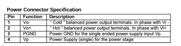
where the bottom portion shows an edge-view of the 1000A board. The four-conductor connector has pin 1 near to the aluminum bar in the middle of the board, and pin 4 near the edge of the board. On the next page, the pins are identified:

Pins 1 & 2 are the speaker outputs, pins 3 & 4 are the power inputs. That means the power inputs (3 & 4) are near the edge of the board, and the speaker outputs (1 & 2 ) are near the central aluminum bar. So the locations of the speaker outputs and the power inputs are reversed compared to the 1000ASP manual (at least as I interpreted the various diagrams).
Bottom line: following the 1000ASP manual's diagram fried my speaker, switching to the assignments in the 1000A manual worked fine, or at least they made music when connected to a speaker. I haven't busted out the ol' oscilloscope yet. My multimeter also supports the 1000A manual's approach.
Perhaps I'm just suffering from undiagnosed dyslexia, and nobody else will have this trouble, but I thought I'd share my experience in case it allows others to keep the smoke contained. Now I can move on to the buffer board and see if I can use the full dynamic range of the modules.
Few
EDIT: It appears my links to the manuals are broken; not sure why. If you search for "ice power 1000asp manual" (NOT the datasheet), and the same thing with 1000a instead of 1000asp, you should be able to find the manuals online.
I thought I had been over-diligent about checking my wiring before testing, but---unless I'm mistaken---I got tripped up by an inconsistency in the Ice Power documentation. I used the manuals for the 1000ASP and 1000A modules to figure out the connections, but it now looks to me like they give conflicting instructions. On the off chance someone else might run into the same trouble, I'll point out where I went wrong. Follow the 1000A manual when wiring up that module!
I first followed what I thought this diagram from page 44 of this 1000ASP manual implies. I have only grabbed the small relevant portion of the diagram:
It shows how to connect the 1000ASP to something like the 1000A (here called "A-series module). Notice the order (left to right) of the group of four connections: first the two speaker outputs, then the two power inputs. Speaker outputs near the edge of the board, and farthest from the 8-pin connector.
If you instead look at the 1000A manual, the diagram on page 4 includes:
where the bottom portion shows an edge-view of the 1000A board. The four-conductor connector has pin 1 near to the aluminum bar in the middle of the board, and pin 4 near the edge of the board. On the next page, the pins are identified:
Pins 1 & 2 are the speaker outputs, pins 3 & 4 are the power inputs. That means the power inputs (3 & 4) are near the edge of the board, and the speaker outputs (1 & 2 ) are near the central aluminum bar. So the locations of the speaker outputs and the power inputs are reversed compared to the 1000ASP manual (at least as I interpreted the various diagrams).
Bottom line: following the 1000ASP manual's diagram fried my speaker, switching to the assignments in the 1000A manual worked fine, or at least they made music when connected to a speaker. I haven't busted out the ol' oscilloscope yet. My multimeter also supports the 1000A manual's approach.
Perhaps I'm just suffering from undiagnosed dyslexia, and nobody else will have this trouble, but I thought I'd share my experience in case it allows others to keep the smoke contained. Now I can move on to the buffer board and see if I can use the full dynamic range of the modules.
Few
EDIT: It appears my links to the manuals are broken; not sure why. If you search for "ice power 1000asp manual" (NOT the datasheet), and the same thing with 1000a instead of 1000asp, you should be able to find the manuals online.
Attachments
Last edited:
Thanks. It had historical and memento-type value, but was over 30 years old. Can’t be replaced, but wasn’t going to the key element of any new designs. Irritating to destroy it—-not the end of the world, though. I felt mildly better when I convinced myself it wasn't purely a case of me being a moron!
- Home
- Amplifiers
- Class D
- Single ended output Open DRC-DA8 into balanced input ICE Power 1000ASP