I've seen that before, isn't it a room analyser.
I was thinking about the Digilent Audio Analyser 2
I was thinking about the Digilent Audio Analyser 2
Install Polarity Checker on your phone. Free and you always have it handy.
The Digilent is way overkill/overpriced for this application.
Jan
The Digilent is way overkill/overpriced for this application.
Jan
The simplest polarity testing is of an unmarked battery . . . you use a DC Voltmeter to measrure it.
When you are done, you can put a piece of masking tape on the unmarked battery and mark the + and the - terminals.
Using a scope to measure polarity of the Hot lead of Power Mains seems a little futile; it has Both + and - polarities, either 50 times a second, or 60 times a second.
Polarity. Because of the mis-understanding of the "polarity" through multiple stages of an amplifier, then perhaps the words Inverting or Non-Inverting of each stage is a better way to describe it.
Perhaps the sine waves drawn on schematics confuses some people.
Instead, draw a unidirectional impulse. It might be less confusing.
Let it start with zero volts, rise to positive volts, and then back to zero volts.
When it goes through an Inverting stage, the result is Very Easy to see and understand.
A positive going impulse that goes through an Inverting stage will look upside down at the output (a negative going impulse: zero volts, negative volts, zero volts).
How about that?
Phase can be more complex than simple polarity, and more complex than simple inverting or non-inverting.
Group Delay is even more complex than phase.
Study each one, from the simplest, to the most complex, and you will be very well equipped.
Last edited:
As this thread was woken up, I thought I'd post an update:
I took some Analog Discovery measurements whilst this was still in its rat's nest stage, so the distortion and hum will be high, getting about 0.6% distortion @1W, mostly 2nd order harmonics, I'm sure once properly built and I play about with the component values it will improve.
Because of work and travel, I've been struggling to finish it; I've made the chassis so far.
The features will be:
Dual round GC9A01 LCD for volume control and measurement display
Dual VU meter with WS2812B backlight
IR sensor for remote
Advanced soft start for PSU
ESP32-S3 for main control
Speaker output control relay to allow me to switch my speakers with my surround sound system
Two additional mini toroidal transformers for MCU and VU Meter
Relay-controlled LFB selector
PGA2311 volume control
I know the main amp works; however, most of the other peripheral circuits are ideas in my head. I have all the components; I've just not had the chance the to design and test them.
A quick update, I'm struggling to find the time to finish this.
I know if I make the amp with just the tubes, resistors, capacitors, etc it will work as I made a prototype. What is taking time is the semiconductor side of it.
So many calculations and theories have been put into the design, no prototypes just design and straight to production, luckily the first few boards have worked the first time. I've taken safety as a design consideration, I'm not an expert but I think I'm doing it all correctly.
I'm just struggling with the VU meter PCB.
I hope the PCB side of all this works, I started this project as an idea 2 years ago.
If you are wondering (probably not), what else I've made you can see the other stuff that I have made on my YouTube channel: https://www.youtube.com/@Ratti3
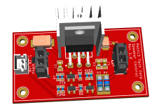
Some pictures, left to right: completed Unregulated Low Noise PSU for PGA2311, ESP32-S3, Mains Soft Start Triac+Relay, Round LCD Panel for display voltages, volume control, etc.
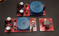
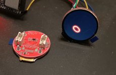
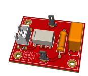
ESP32-S3 Control Board with low noise DC regulators, Input Selector, and Negative Feedback
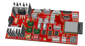
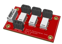
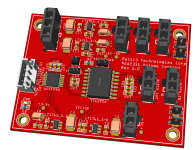
PGA2311 Volume Control with low noise LDO regulators, Speaker Output Relay control board
I know if I make the amp with just the tubes, resistors, capacitors, etc it will work as I made a prototype. What is taking time is the semiconductor side of it.
So many calculations and theories have been put into the design, no prototypes just design and straight to production, luckily the first few boards have worked the first time. I've taken safety as a design consideration, I'm not an expert but I think I'm doing it all correctly.
I'm just struggling with the VU meter PCB.
I hope the PCB side of all this works, I started this project as an idea 2 years ago.
If you are wondering (probably not), what else I've made you can see the other stuff that I have made on my YouTube channel: https://www.youtube.com/@Ratti3
Some pictures, left to right: completed Unregulated Low Noise PSU for PGA2311, ESP32-S3, Mains Soft Start Triac+Relay, Round LCD Panel for display voltages, volume control, etc.


ESP32-S3 Control Board with low noise DC regulators, Input Selector, and Negative Feedback


PGA2311 Volume Control with low noise LDO regulators, Speaker Output Relay control board


Thanks for the comments and feedback.
I did consider fewer individual PCBs but it was not always possible, this is due to the layout of the enclosure and certain things link PSUs, feedback relays have to be in certain locations.
I have designed it so the AGND and DGND are separate and AGND connections are solderable to the PCBs, most of the connectors are digital signals or low current relay connectors. All DC connections are heavy-duty connectors. Some of the connectors have gold flashed pins. The audio connectors are also solderable.
The amp itself will be point-to-point wiring with push-back wires.
The proof will be in the pudding when I assemble it all, I think I'll have it built by summer.
I've done 95% of the analogue circuit assembly and tested with none of the digital PCBs installed, so far so good. I did change the tube design, as I had the holes already made I ended up paralleling the driver stage when I decided not to use the EF86.
This is the AD2 results, no global NFB applied so the distortion is higher than expected, I need to swap tubes to see if that is the reason why there are slight left and right channel differences.
Frequency response is good, about 0dB 10-10KHz @ 2.5W, -1dB @20KHz
THD vs Power, I only measured to 10W, got less than 1%@1W, 1.5%@2W, and 5%@10W
Attachments
- Home
- Amplifiers
- Tubes / Valves
- Single Ended Phase Clarification


