Yes, it is the 3M 74 film. But for the tweeter I am using a 60 mm wide tape.Hej Solhaga you still use the 3m material ? or what did you use as membrane?
Yes, it is the 3M 74 film. But for the tweeter I am using a 60 mm wide tape.
thx i forgot the type and i know the original thread we where talking amts was pretty big haha 🙂
I don't know why, but the 3rd harmonic box was not checked in the measurements above.
I have updated the pictures above, but you'll probably see the old ones due to web browser caching.
So here there are again.
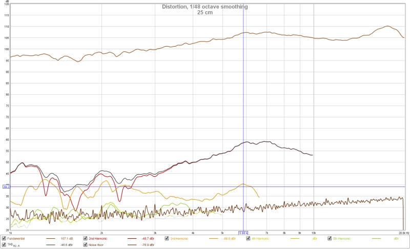
At 25 cm:
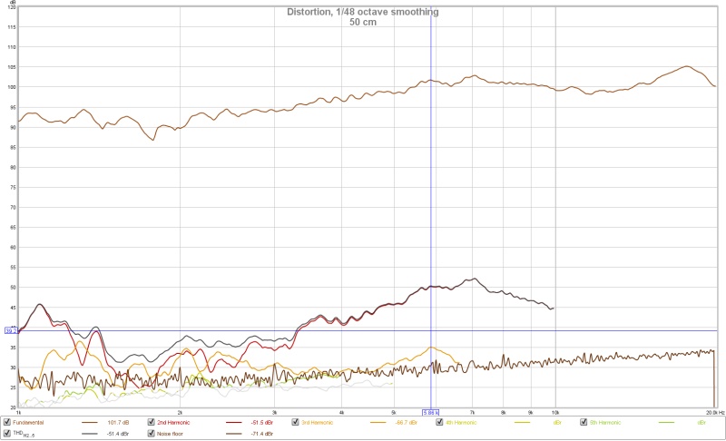
At 50 cm:
At 100 cm.
3rd harmonic in the noise floor!
I have updated the pictures above, but you'll probably see the old ones due to web browser caching.
So here there are again.
At 25 cm:
An externally hosted image should be here but it was not working when we last tested it.
At 50 cm:
An externally hosted image should be here but it was not working when we last tested it.
At 100 cm.
An externally hosted image should be here but it was not working when we last tested it.
3rd harmonic in the noise floor!
ah ok 🙂 it looks really nice ! very smooth to !. i asked what kind of mic since the umik-1 has a bit higher noise floor then some others. witch could explain the 3rd harmonic going under in
the noise 🙂 still really nice though! you can set rew to Percentage distortion, it gives and easier way of reading the distortion (at least i think so) you can change it in the settings logo on the right top corner. you probable already knew but ok.
the noise 🙂 still really nice though! you can set rew to Percentage distortion, it gives and easier way of reading the distortion (at least i think so) you can change it in the settings logo on the right top corner. you probable already knew but ok.
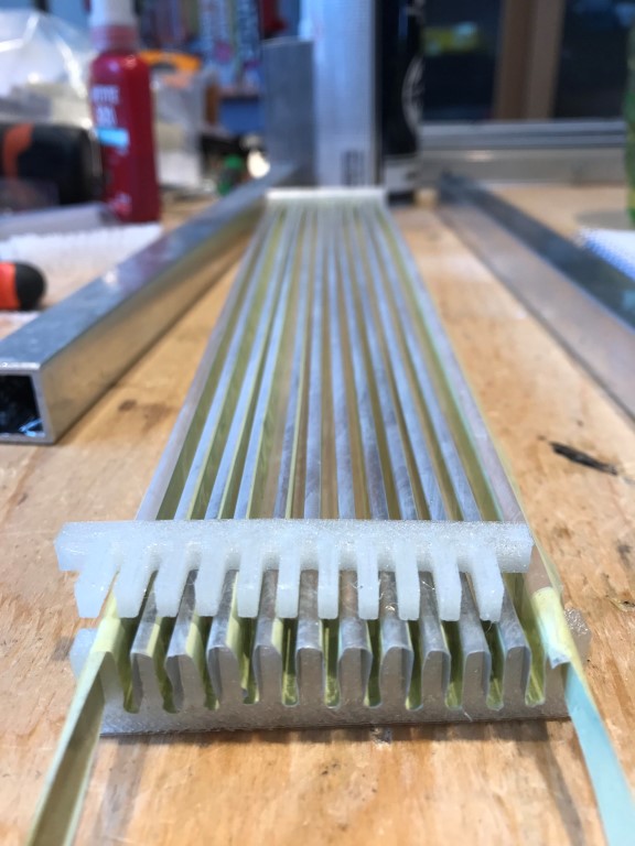
The mid membrane is a little bit larger, so a larger folding tool is required:
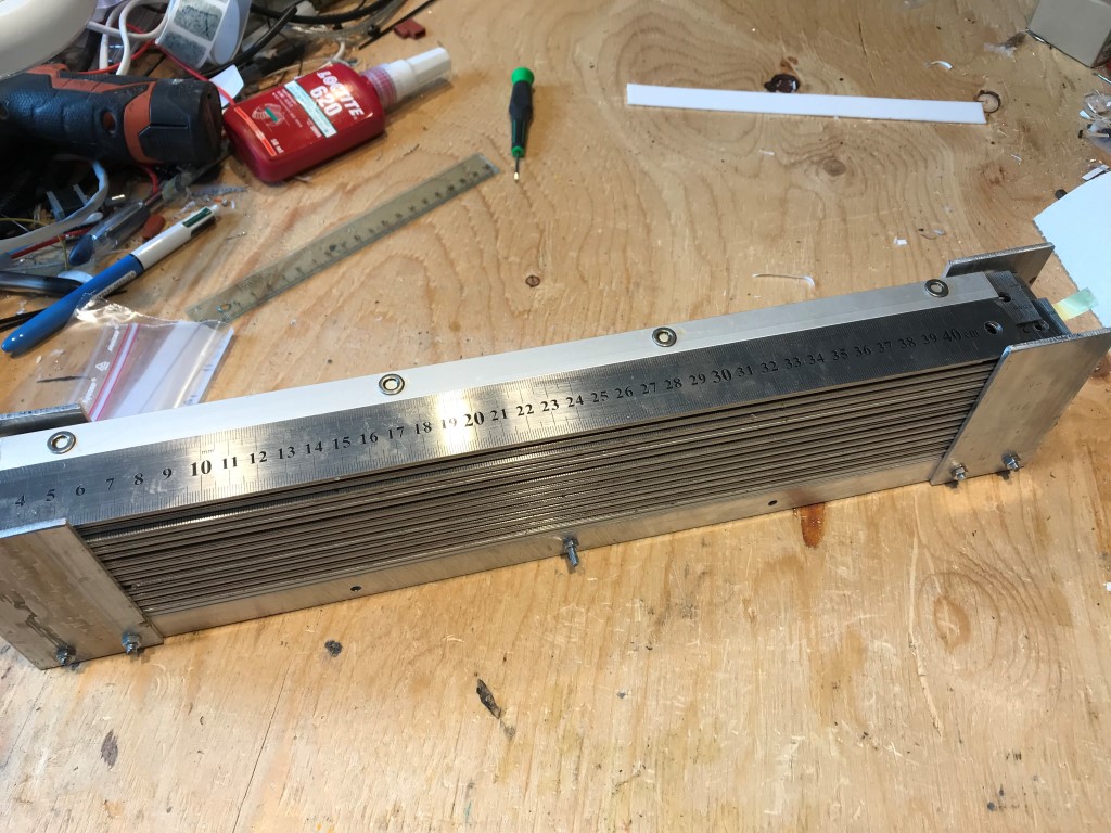
Out of the oven:
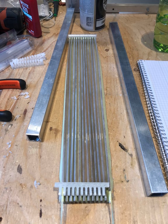
3D printed ends makes the mounting a lot easier:
I will have two of a thinner variant of the ends as support in the middle.
The distortion levels will go down and the folds will be more even.
I will probably fix the sides of the membrane towards the magnets with silicone.
But I haven't decided yet, first I must find out how it measure...
Out of the oven:
3D printed ends makes the mounting a lot easier:
I will have two of a thinner variant of the ends as support in the middle.
The distortion levels will go down and the folds will be more even.
I will probably fix the sides of the membrane towards the magnets with silicone.
But I haven't decided yet, first I must find out how it measure...
Mounted and measured:
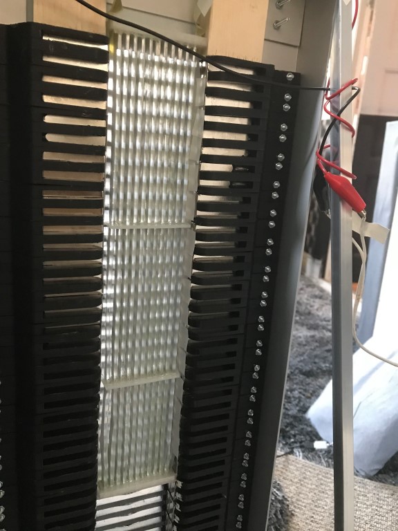
With not yet fully optimized back pole pieces and only taped membrane sides:
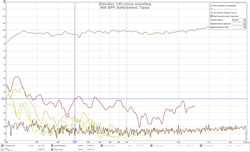
SPL 99 dB @ 1 Watt, 2nd harmonic -45 dB (~0,5 %) and 3rd harmonic -59 dB (~0,1 %).
Intended frequency range of the mid membrane is 350 Hz to 3400 Hz with -24 dB/octave filters.
With not yet fully optimized back pole pieces and only taped membrane sides:
SPL 99 dB @ 1 Watt, 2nd harmonic -45 dB (~0,5 %) and 3rd harmonic -59 dB (~0,1 %).
Intended frequency range of the mid membrane is 350 Hz to 3400 Hz with -24 dB/octave filters.
You're a certified genius. I wish I had the skills to do the CAD & 3D prints like this! The distortion plots are very, very impressive. Do you plan to cross this over to a woofer for the midbass?
Thank you Jamii.
I've learned a lot from a fellow countryman of yours and his Youtube channel Maker's Muse.
Here are the planned cross over frequencies:
CABS : 10 - 100 Hz
Woofer : 40 - 350 Hz
Mid: 350 - 3400 Hz
Tweeter: 3400 -20 kHz
The four loudspeakers for CABS have AE's TD15H and so does the two woofers.
I've learned a lot from a fellow countryman of yours and his Youtube channel Maker's Muse.
Here are the planned cross over frequencies:
CABS : 10 - 100 Hz
Woofer : 40 - 350 Hz
Mid: 350 - 3400 Hz
Tweeter: 3400 -20 kHz
The four loudspeakers for CABS have AE's TD15H and so does the two woofers.
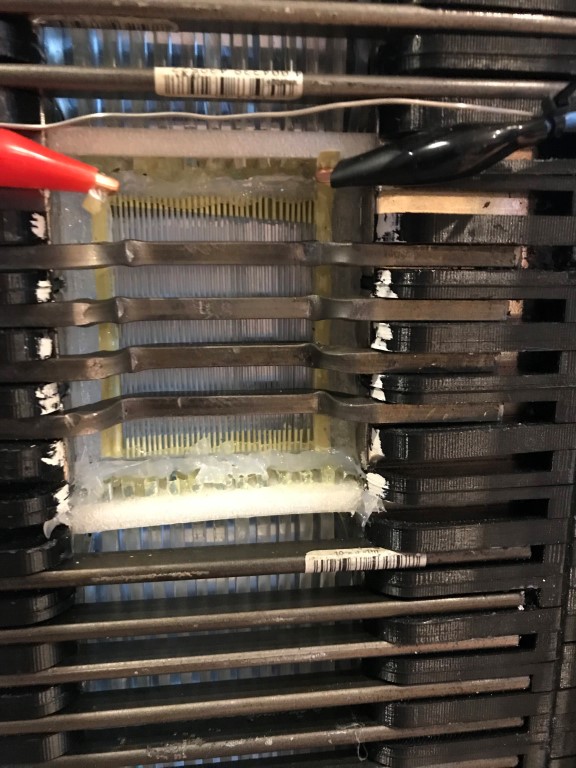
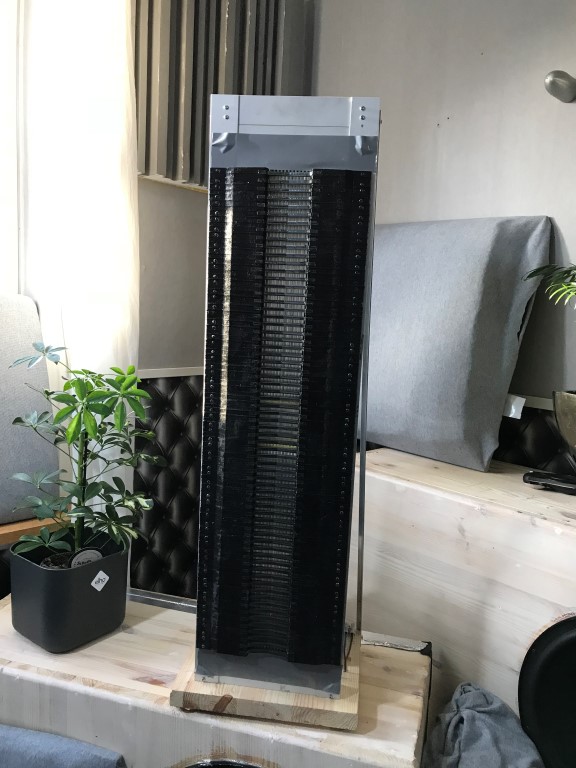
Mounting of the tweeters with back pole pieces bowed down so they are near the membrane:
Time for the first listening test!
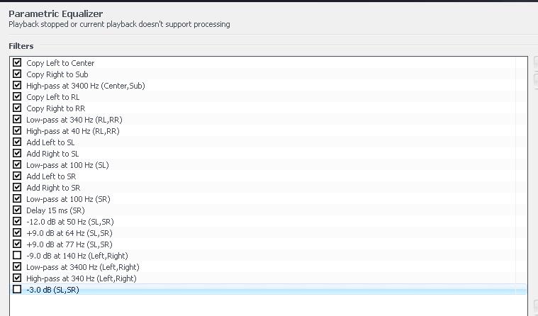
But first some basic DSP settings:
I will listen to this a couple of days before I start measuring, perhaps the individual levels needs to be adjusted.
First impressions though is that the dispersion now is good in the high frequencies and that the music fills the whole room.
So this is SLAM! in the listening room:
Left:
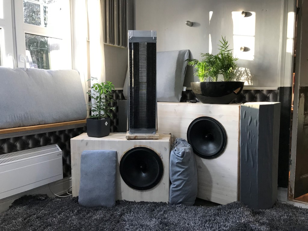
Right:
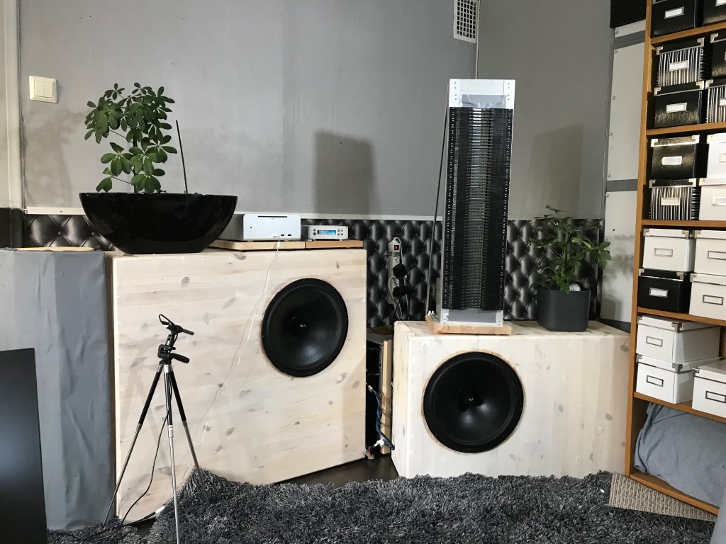
Close up left:
Still have some cosmetics to take care of; the gray gaffa tape is not fun to look at.
Time for the first listening test!
But first some basic DSP settings:
An externally hosted image should be here but it was not working when we last tested it.
I will listen to this a couple of days before I start measuring, perhaps the individual levels needs to be adjusted.
First impressions though is that the dispersion now is good in the high frequencies and that the music fills the whole room.
So this is SLAM! in the listening room:
Left:
Right:
Close up left:
Still have some cosmetics to take care of; the gray gaffa tape is not fun to look at.
- Status
- Not open for further replies.