Would the buffer be before the IPS input, behind the pot or vice versa? Could it be a digital control? How about something that could be used on ALL the IPS that have been created or for the future.I have this buffer http://www.diyaudio.com/forums/anal...s-simple-error-correction-superbuffer-28.html i want to use this in combination with a volume potentiometer .
I wonder witch IPS is more suitable for this.
Opinions please.
Pete
Can you post you asc file on you OPS, I would Like to see how its possible to shape the class A to B transition, I think I have some idéas on how to improve that area significantly
/Michael
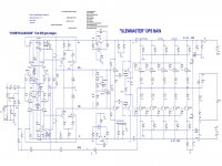
http://www.diyaudio.com/forums/atta...95-slewmaster-cfa-vs-vfa-rumble-wolverine.asc
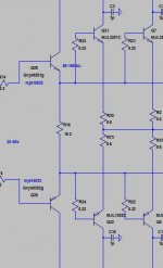
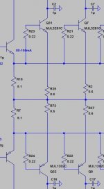
Ok.... Here goes. Two ways of running the output transistors (same bias). the EF3 (OPS-1) and EF2+biased dumpers (OPS-2)
I really think this need to be researched a lot more. Its really a lot better when the drivers are assisting the turn on and turnoff of the output transistors. I know the is rude and rough, but the mechanism is there...one is not really turning off, the other is, well nA is not really a lot compared to the 500uA or 1/2mA in the EF2 dumping.
I really think this need to be researched a lot more. Its really a lot better when the drivers are assisting the turn on and turnoff of the output transistors. I know the is rude and rough, but the mechanism is there...one is not really turning off, the other is, well nA is not really a lot compared to the 500uA or 1/2mA in the EF2 dumping.
Attachments
Last edited:
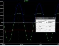
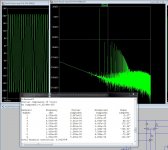
If the peak Ie is ~275mA in both pictures, then it is obvious the bias has increased in the second picture, just look at the crossover points. Otherwise, in the second picture the peak Ie has decreased, which again would show better crossover appearance, regardless of any other special circuitry.
symetri cascode
I added cascodes to the symetri topology input stage, which allowed using lower break-down BC550C and BC560C input transistors. Harmonic distortion was lowered. What's a few more transistors among friends")
I added cascodes to the symetri topology input stage, which allowed using lower break-down BC550C and BC560C input transistors. Harmonic distortion was lowered. What's a few more transistors among friends
Attachments
LineSource
In my opinion there is no need to putt another cascode into symetri amp. Look at post:
http://www.diyaudio.com/forums/solid-state/248105-slewmaster-cfa-vs-vfa-rumble-165.html#post4390928
The real life measurements (numbers) are so good that now only good and proper listening tests + some adjustment can only make and improvement.
The BC550/560 I think are not so low noise in real life, I have used KSC1845/KSA992 with better resault and without cascoding them.
I think that if circuit is well designed, better is to leave it SIMPLE and just tweak a bit the currents and gain stages.
Ofcourse I could be wrong, but this is only my 3 cents.
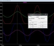
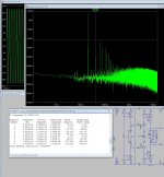
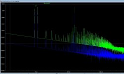
Now this is a rumble....!!
And this may be the reason why CFA just don't cut it for me.
With one tone they are close to identical in performance, but when the higher frequency content rides on top of a lower frequency larger amplitude sine (like the frequency distribution in music) CFA's seems to invent more side bands, and thus generate more IMD content.
Blue is the FFT of the signal going into the amplifier green is at the output,
Both amplifiers share the same OPS
input is:2V in at 1KhZ and 0.5V in at 15KHz.
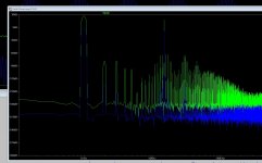
Attachments
Last edited:
This is simulation, i have No tools that can make this kind of Real life measurement . But but both amplifiers have been built and listened to. In fact several CFA's have been built from simple VSSA types owner more advanced versions with diamond and current mirrors. I have also built VFA , from blameless to leach types.
Oh, yes ?but when the higher frequency content rides on top of a lower frequency larger amplitude sine (like the frequency distribution in music) CFA's seems to invent more side bands, and thus generate more IMD content.
Exactly the contrary of what everybody experienced (including myself)... And contradict all theories about the influence of slew-rate on TIM in negative feedback loops.
Last edited:
CFA Slev yes Good, but something NOT very good and voltage current mixing going on in the feedback node. CFAs always end in a thermal compromise between low impedance and power dissipation. The large amplitude low frequency pushes this feedback non-linearity and the higher frequencies suffer. I have been very very pro for the CFA, but I have to admit that they lack drive and bite in the base, why I don't know for sure, This indicates some differences. I'll try over the next weeks to get some tools I can use in real life, need to generate some multi tone test tones, then an IRL FFT can be made.
Now this is a rumble....!!
input is:2V in at 1KhZ and 0.5V in at 15KHz.
Interesting finding. Was there any chance the amps involved in the simulation were approaching clipping at those input levels? Could it be possible to simulate them at a lower input level, say, 6 or 10 db down?
I don't understand, voltage and currents are two ways to look at the same events.voltage current mixing going on in the feedback node
If it was the the same, then the behavior of the CFA wouldn't change with the impedance of the feedback network. CFA's are expansive of nature, that could come with a prize.
Nattwa, they are far from clipping, signal is only 1/3 of the rail voltage. I suspect with increased swing the effect will be even greater, and off-course less with lower signals.
But then again some Real life testing is needed.
Nattwa, they are far from clipping, signal is only 1/3 of the rail voltage. I suspect with increased swing the effect will be even greater, and off-course less with lower signals.
But then again some Real life testing is needed.
Last edited:
- Home
- Amplifiers
- Solid State
- Slewmaster - CFA vs. VFA "Rumble"