bear in mind also that all points of the circuit exposes you to the 230 volt mains...
so unless you really know what you are doing, then better try something else....
so unless you really know what you are doing, then better try something else....
timing +-10% would be good.
+-20% would be acceptable.
+-50% would be just about workable.
with +-6% on mains voltage, you won't get within +-50%, unless you have a very robust shunt regulator to prevent overvoltage.
That's what your Zener is doing !
+-20% would be acceptable.
+-50% would be just about workable.
with +-6% on mains voltage, you won't get within +-50%, unless you have a very robust shunt regulator to prevent overvoltage.
That's what your Zener is doing !
Yes, the Zener is the Shunt regulator.
The change in excess current as mains voltage changes is large.
The change in excess current as mains voltage changes is large.
I thought that was the raison d'etre for a Zener. Anyway, the circuit provides +-12% variance given a +10%/-6% mains. Is that so bad in this context? It's just outside of your "good".
I have more of a problem with this site posting a circuit and BoM without noting components listed are mains dependent. Also, adding comments to the BoM which points new guys like me towards C2 as the principal component to change in order to adjust timing is rather annoying.
I have more of a problem with this site posting a circuit and BoM without noting components listed are mains dependent. Also, adding comments to the BoM which points new guys like me towards C2 as the principal component to change in order to adjust timing is rather annoying.
... adding comments to the BoM which points new guys like me towards C2 as the principal component to change in order to adjust timing is rather annoying.
"Trust, but verify." Доверяй, но проверяй
(citation)
"Trust, but verify." Доверяй, но проверяй
(citation)
C2 as the principal component to change in order to adjust timing is rather annoying.
think of C2 like this, increasing its value
lowers its impedance and increases charging current....
now, increasing charging current to C3 makes for a faster charge build up....
increasing the value of C3 lengthens the charging time....and vice versa...
my rule of thumb for C2, use the lowest value that you can get away with,
just enough to activate the relay and still have some current for the zener.....
adjust the value of C3 for shorter or longer delays...
for the spark quenching cap C1, at least 2kv ceramic disc type...
caps do not have any idea what circuit they are used in.....
you do not even have to use caps that are "made for ac" , it is
enough that the cap voltage ratings are 400vdc for 120 volt mains,
630vdc or 1000vdc for 230 volt mains...
and i will select those caps that are well encapsulated....
btw, this type of circuit was first used in the tube amp era in the 50's
and was used to derive negative bias for output tubes....
even though i have 40 years of experience, this type of circuit scares me...
this the reason i never used this type of circuit...
this is what i use instead.....safer to use....

Related to this is the slow charge circuit.
On which side of the toroid should you install the slow charge? Primary or secondary?
On which side of the toroid should you install the slow charge? Primary or secondary?
Lets say I have a diyaudio soft start as well.
How would this be sequenced with the slow charge?
I am confused as to how the that could be made to work. 😕
How would this be sequenced with the slow charge?
I am confused as to how the that could be made to work. 😕
Slow charge circuit? Slow charging of what? In contrast to Andrew's position, I can't decouple the charging of the magnetic flux in the transformer and charging of filter capacitance (and in some cases, load capacitance). Unless one disconnects the two, a current limiter manages the charging of both. Just set the timing accordingly.
BTW I have redone the board above to fix the replacement of LED3 with a diode, make some of the pads larger and so easier to solder, align the rectifier diodes around the same way and reroute the trace that went underneath the relay. I will post the berbers at some point in case they're of interest to others.
BTW I have redone the board above to fix the replacement of LED3 with a diode, make some of the pads larger and so easier to solder, align the rectifier diodes around the same way and reroute the trace that went underneath the relay. I will post the berbers at some point in case they're of interest to others.
Related to this is the slow charge circuit.
On which side of the toroid should you install the slow charge? Primary or secondary?
On the secondary side.Primary
All the Power NTC manufacturers show the NTC in series with the capacitance that needs current limiting.
None show the current limiting NTC on the other side of a power transformer from the capacitance.
in my 6C33 pp amp build, http://www.diyaudio.com/forums/tubes-valves/265229-tonys-6c33-pp-amp-build-progress.html i used a total of 3.6k omh resistors to charge 4,000ufd 400v filter caps to about 270 volts, this is secondary side and the resistor is shorted out by relay after about 2 minutes....http://www.diyaudio.com/forums/tubes-valves/265229-tonys-6c33-pp-amp-build-progress.html
Slow charge circuit? Slow charging of what? In contrast to Andrew's position, I can't decouple the charging of the magnetic flux in the transformer and charging of filter capacitance (and in some cases, load capacitance). Unless one disconnects the two, a current limiter manages the charging of both. Just set the timing accordingly.
BTW I have redone the board above to fix the replacement of LED3 with a diode, make some of the pads larger and so easier to solder, align the rectifier diodes around the same way and reroute the trace that went underneath the relay. I will post the berbers at some point in case they're of interest to others.
Soft start is for STARTING the transformer.
This is done by inserting a current limiter in the primary circuit to limit the MAIN's current that flows during the transformer's starting period. This duty is completed in at most a dozen cycles of the Mains supply. Some data shows it can be substantially completed in as few as 4 cycles.
Generally switching the current limiting resistance out after ~ 200ms is appropriate.
Slow charging of the smoothing capacitance is there to limit damaging currents from passing through the rectifiers and into the capacitors.
This current limiter needs many seconds "in circuit" to allow the capacitors to nearly reach fully charged state.
Using a 4r power resistor and 20mF of capacitance results in an RC time constant of 80ms. i.e. the capacitor will be charged to just over 60% of final value in about 80ms.
It will be within a percent or two after 10*RC i.e. 800ms to reach ~99% of final voltage.
Double the current limiter resistance, to halve the peak charging current and this charging time will be doubled.
Double the capacitance and the charging time will be doubled.
Combine both and the 10*RC becomes 3.2seconds.
Decide on your acceptable peak charging current. Calculate the resistance required to limit the current to that value for the emf you have from the transformer secondary.
An NTC starts with a high resistance, as the charging current heats up the NTC, it's resistance drops significantly. This allows the charging current to be maintained nearer the peak charging current. The effect of this reducing resistance is that charging time reduces.
Last edited:
An NTC starts with a high resistance, as the charging current heats up the NTC, it's resistance drops significantly.
majority of my NTC's in my parts bin are 4 or 5 ohms when cold and below 1 ohm when hot and passing current....
As slow charge limiters they don't maintain a high enough current for long enough to get down to the lowest resistances.
They could start cold @ 5r and drop to 2r to 3r when warmed and then start increasing in resistance as full charge is approached and be almost back to the cold resistance when the slow charge period is completed. It's the return to the near cold resistance that requires the bypass to be activated to reduce the source impedance seen by the PSU.
You seem to have found the same when you reported
Removing the high value resistance after it has done it's job and get a low source impedance for the PSU.this is secondary side and the resistor is shorted out by relay after about 2 minutes
Last edited:
Soft start is for STARTING the transformer.
This is done by inserting a current limiter in the primary circuit to limit the MAIN's current that flows during the transformer's starting period. This duty is completed in at most a dozen cycles of the Mains supply. Some data shows it can be substantially completed in as few as 4 cycles.
Generally switching the current limiting resistance out after ~ 200ms is appropriate.
Slow charging of the smoothing capacitance is there to limit damaging currents from passing through the rectifiers and into the capacitors.
This current limiter needs many seconds "in circuit" to allow the capacitors to nearly reach fully charged state.
Using a 4r power resistor and 20mF of capacitance results in an RC time constant of 80ms. i.e. the capacitor will be charged to just over 60% of final value in about 80ms.
It will be within a percent or two after 10*RC i.e. 800ms to reach ~99% of final voltage.
Double the current limiter resistance, to halve the peak charging current and this charging time will be doubled.
Double the capacitance and the charging time will be doubled.
Combine both and the 10*RC becomes 3.2seconds.
Decide on your acceptable peak charging current. Calculate the resistance required to limit the current to that value for the emf you have from the transformer secondary.
An NTC starts with a high resistance, as the charging current heats up the NTC, it's resistance drops significantly. This allows the charging current to be maintained nearer the peak charging current. The effect of this reducing resistance is that charging time reduces.
A soft start is nothing other than a current limiter. You can place a current limiter wherever you choose - either permanently or temporarily by switching it out after time x - for whatever purpose you need.
To avoid continuous repetition....
Let's say you like Mundorf M-Lytic smoothing caps. Big fat ones. 22,000uF with a rated ripple at Tmax and 100Hz of 5.4A. Over what time period would you measure RMS current through the capacitors to see if it fell below their ripple rating? The first second, half second, some shorter period? Recognising that the longer the period the lower the result.
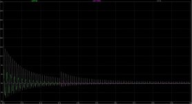
I have attached some outputs from the simulation of a power supply I have been working on. It has two 21H transformers and over 0.2F of capacitance to be charged. It includes my current limiter circuit. Peak UK mains supply (358V peak) and 90 degree starting phase for worst in-rush.
Green is the primary side current going through the NTC. Pink is the primary side current going through the NC contact of the relay. You can see that the current limiter switches out after 300ms. At this point the NTC is still restricting mains current flow. Grey is the current through the first-in-line caps (i.e. those taking the brunt of current flow.
Have I exceeded the 5.4A ripple rating of the caps?
RMS current through the caps simulates as:
Over first second: 2.534A
Over first half second: 3.573A
Over first quarter second: 4.951A
Over first 100ms: 7.35A
Attachments
Last edited:
- Home
- Amplifiers
- Power Supplies
- Soft start circuit design and other psu issues