If there is not serious possibility to burn the DAC, then I don't mind to spend 20 euros or something more to give it a try.
LeeHooker,the question is, is it necessary for the player to work normally + spdif input through the i2s switch or only as spdif of the DAC? Then you only need to switch the data, lrck and bclk. Pin3 - CKSL - do not touch.
The first step will be without the CD.
Which receiver would you suggest?
DIR9001 Module Digital Receiving Board Coaxial USB to I2S Output|Air Conditioner Parts| - AliExpress
DIR9001Mini Receiving Board Support 384fs Clock For DAC Amplifier|Digital-to-Analog Converter| - AliExpress
The first one it has 2 inputs (coax + USB) which is very useful.
The second, comes without digital filtering. As far as there is digital filter on the existing DAC, does it needed to be on the receiver board?
Try to keep it as simple as possible.
I do not see digital filtering in any of these boards, it is the clock frequency they are talking about.
BTW 右 is the word for "right" like in right justified.
I do not see digital filtering in any of these boards, it is the clock frequency they are talking about.
BTW 右 is the word for "right" like in right justified.
So, which is the most simple board? The green one that has 2 I2s outputs or the blue with 2 inputs?
Digital things are chinese to me and (unfortunately) not greek 🙂
Digital things are chinese to me and (unfortunately) not greek 🙂
The one with 1 input.
Funny thing is that there is an option to put in a DF. Did you see which one they are using here?
Funny thing is that there is an option to put in a DF. Did you see which one they are using here?
Last edited:
I can see only in brown board that is connected to PD0036. Without jumber on the receiver board.
There are also 2 options. With or without audio transformer. What's the difference?
There are also 2 options. With or without audio transformer. What's the difference?
Last edited:
OK.
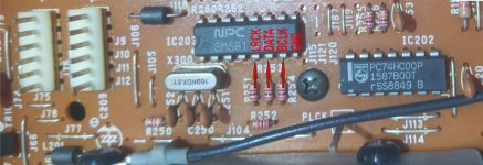
I did the connection diagram.
Do I have to connect before or after the resistors? (Point 1 or point 2?)
I did the connection diagram.
Do I have to connect before or after the resistors? (Point 1 or point 2?)
Attachments

I would use pin one, but they need to be off the board, no connection to the CDX1125.
Checkout these pictures from the manual, it is for the 910 and 810 and uses different DF's but the same circuit.
Checkout these pictures from the manual, it is for the 910 and 810 and uses different DF's but the same circuit.
Attachments


LeeHooker, when connecting the spdif receiver DIR9001
to filter SM5817,
connect all outputs from the dir to the resistors by removing them from the board, and leaving the connection only from the filter side (lrck-r251, data-r252, bclk-r254).
If there is no sound at the output, it may be necessary to switch the date from r252 to r253, eliminating the inversion of this signal. You can also remove the quartz from the inputs 1,2 of the filter and bring the MCLk signal output the dir to pin 1 of the SM5817 .
OK. So...
RECEIVER to SM5817
Gnd ------------> Gnd
MCLK ----------> Pin1 (unsoldered - on air)
Pin2 (unsoldered - on air)
LRCK -----------> R251 (on air) ---------> Pin5
BLK ------------> R254 (on air) ----------> Pin7
DATA -----------> R252 (on air) ---------> R253 ------> Pin 6
If no signal then
DATA -----------> R253 (on air) ---------> Pin 6
You need to add a 50-100 Ohm resistor to the master clock circuit, connecting one pin to pin1 SM5817, the second to the output from DIR9001 - MCLK out
RECEIVER to SM5817
Gnd ------------> Gnd
MCLK ----------> 100 Ohm ----------> Pin1 (unsoldered - on air)
Pin2 (unsoldered - on air)
LRCK -----------> R251 (on air) ---------> Pin5
BLK ------------> R254 (on air) ----------> Pin7
DATA -----------> R252 (on air) ---------> R253 ------> Pin 6
If no signal then
DATA -----------> R253 (on air) ---------> Pin 6
Yes. But I must disconnect the pin2 and leave it free. Isn't it?
Or I must do nothing and leave it there connected as it is?
Or I must do nothing and leave it there connected as it is?
Yes, pin 2 should be left free. You need to disconnect quartz 16,9244 Mhz from pin 1 and pin 2 SM5817, if you connect mclk with DIR9001 to filter 5817.
Well, it's been a long time since I started this thread. I put the project aside and after some years I came back 🙂
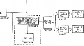
Since then, some things changed like the M/B of my pc. My intention is to take the input signal from a PC, through the SPDIF output via a DIR9001 receiver to I2S output. Then, the I2s will go to SM5807 digital filter of my old cd player.
But my new M/B doesn't provides SPDIF output, so I have to use the USB port and a USB to I2s receiver.
There is also an HDMI output, so I could use an HDMI to I2s receiver, but I've read that this is not a good option.
Can you please tell me if any of the receivers below are proper for what I want to do?
USB to I2S IIS
USB Sound Card USB To Coaxial Fiber I2S
USB Digital Interface USB To Digital Audio I2S DSD SPDIF Output
Of course, I know that there are some very good options like I2SoverUSB but I'm looking if it's possible to find a cheap solution, otherwise I will go for a new DAC.
- Home
- Source & Line
- Digital Source
- SPDIF input in DENON DCD-910A?