Don't use a scope probe to measure unknown voltages.Hi Andrew...
I tried to wire it up, with an dual secundary transformer i have.
Everything is working now, and railvoltages are fully stable -12/0/+12.
Unfortunately i have no oscilloscope right now, but meassuring AC on rails shows practially zero mv.
So it is working as bipolar supply also with this setup. So something happening when using single rails transformer! So it must have something to do with missing transformer winding isolation between pos./neg. Regulator?
Jesper
The scopes grounding link will short any point to the PE of the maisn. That is more likely to blow up amplifiers than many other mistakes you could make.
Use an ISOLATED Voltmeter to measure unknown voltages. In this context an isolated voltmeter is any battery operated one, or a mains powered one that has the test probes truly isolated from the mains.
Don't use a scope probe to measure unknown voltages.
The scopes grounding link will short any point to the PE of the maisn. That is more likely to blow up amplifiers than many other mistakes you could make.
Use an ISOLATED Voltmeter to measure unknown voltages. In this context an isolated voltmeter is any battery operated one, or a mains powered one that has the test probes truly isolated from the mains.
Andrew... Please read my post again...
I did not read any unknown voltage.. Just ac on dc line (ripple)
Jesper.
You posted
That gives the impression that if you had a scope you would have used it to measure your voltage.Unfortunately i have no oscilloscope right now, but meassuring AC on rails shows practially zero mv.
I tried to wire it up, with an dual secundary transformer i have.
Everything is working now, and railvoltages are fully stable -12/0/+12.
Nice to know you succeeded

Andrew, Salas 
Just wanna tell, that my DAC survived...
https://www.youtube.com/watch?v=59iTmTM6Nm0
Jesper.
Just wanna tell, that my DAC survived...
https://www.youtube.com/watch?v=59iTmTM6Nm0
Jesper.
Hi.
I tried to meassure the CCS and the actual current, which is drawn by the DAC's +12/0/-12 supply, and the calculations are :
+12VDC rail : 2.7mV / 0.1ohm = ~27mA
+12VDC rail : Meassured with DMM in mA seriel connected probes ~30mA
-12VDC rail : 2,9mV / 0.1ohm = ~29mA
-12VDC rail : Meassured with DMM in mA seriel connected probes ~30mA
Voltage drop at R101 (positive rail) = 1.0400VDC / 4.22ohm = 246mA CCS
Voltage drop at R202 (negative rail) = 0.909VDC / 4.22ohm = 215mA CCS
DiyinHK states that two +12/-12 v supplys > 100mA must be used, but they are not using near that current i see
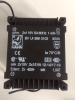
I did find some 2x15v (30VA) Hahn trafo i had in a box at my little shop, and by the calculations i find it must suitable for this setup, eventhrough the BIB build papers states 50VA.
The HAHN is 2x15vac rails / 1000mA each (15VA*2), and by my meassurements the SSLV's is using only say maximum 250mA(CCS)+100mA for the regulators and rest of circuit. So maybee it will end up with 1/3 of the maximum load for the trafo?
Is this fully good enough, or am i missing something here?
Jesper.
I tried to meassure the CCS and the actual current, which is drawn by the DAC's +12/0/-12 supply, and the calculations are :
+12VDC rail : 2.7mV / 0.1ohm = ~27mA
+12VDC rail : Meassured with DMM in mA seriel connected probes ~30mA
-12VDC rail : 2,9mV / 0.1ohm = ~29mA
-12VDC rail : Meassured with DMM in mA seriel connected probes ~30mA
Voltage drop at R101 (positive rail) = 1.0400VDC / 4.22ohm = 246mA CCS
Voltage drop at R202 (negative rail) = 0.909VDC / 4.22ohm = 215mA CCS
DiyinHK states that two +12/-12 v supplys > 100mA must be used, but they are not using near that current i see
I did find some 2x15v (30VA) Hahn trafo i had in a box at my little shop, and by the calculations i find it must suitable for this setup, eventhrough the BIB build papers states 50VA.
The HAHN is 2x15vac rails / 1000mA each (15VA*2), and by my meassurements the SSLV's is using only say maximum 250mA(CCS)+100mA for the regulators and rest of circuit. So maybee it will end up with 1/3 of the maximum load for the trafo?
Is this fully good enough, or am i missing something here?
Jesper.
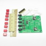
Attachments
The ClassA stages draw a quiescent current that you can measure.
The ClassA stages do not draw a constant current when delivering some AC current to a load.
This variation in current draw is not easy to measure.
If you allow for a succession of ClassA stages to have a total draw of 27mA, then when those stages are drawing maximum ClassA output through each stage, you will find that the peak current draw is double the quiescent draw.
But that is a big over-estimate, because you are very unlikely to ever get all the ClassA stages to hit their maximum ClassA and almost never do that at the same time.
So it is very safe to assume the absolute worst case current is 54mApk (and some of this peak current comes from the local supply rail decoupling). The regulator just recharges that decoupling ready for the next peak transient.
Setting the CCS of a Shunt regulator to a bit more than this allows, the system to never current clip. 60mA to 70mA would do, but nothing wrong with using 100mA.
Now moving to a suitable transformer rating.
For a 100mAdc maximum current draw that through a Shunt regulator becomes a 100mA continuous current draw, you must select a transformer with a 200mAac rating and this will run hot. For cool operation select double that rating, i.e. 400mAac.
For a dual 15Vac secondary you have a VA rating of {15vac+15vac}*0.4Aac = 12VA
Anything bigger than 11VA will do.
Last edited:
I did find some 2x15v (30VA) Hahn trafo i had in a box at my little shop, and by the calculations i find it must suitable for this setup, eventhrough the BIB build papers states 50VA.
The HAHN is 2x15vac rails / 1000mA each (15VA*2), and by my meassurements the SSLV's is using only say maximum 250mA(CCS)+100mA for the regulators and rest of circuit. So maybee it will end up with 1/3 of the maximum load for the trafo?
Is this fully good enough, or am i missing something here?
Jesper.
By coincidence I have those same 30 VA HAHN, difference is its the 18V+18V model, in my DCG3. At 110mA steady draw for each one they were running rather hot at 43C when just standing on the bench with their pins because they are small and packed in resin but after I mounted them in the chassis where they had a plexiglass mounting surface to touch their bellies to and that absorbed some dissipation they went down to 38C.
By coincidence I have those same 30 VA HAHN, difference is its the 18V+18V model, in my DCG3. At 110mA steady draw for each one they were running rather hot at 43C when just standing on the bench with their pins because they are small and packed in resin but after I mounted them in the chassis where they had a plexiglass mounting surface to touch their bellies to and that absorbed some dissipation they went down to 38C.
For now i only tried for 15-20min. At that time it did not get warm at all.
I will ofcause report back, but i need some more sinking for my setup now i guess
 ... This project wasent even supposed to be done until Fall/winther!, but due to cold weather here in DK, i find myself doing so otherwise i think
 Jesper.
The ClassA stages draw a quiescent current that you can measure.
The ClassA stages do not draw a constant current when delivering some AC current to a load.
This variation in current draw is not easy to measure.
If you allow for a succession of ClassA stages to have a total draw of 27mA, then when those stages are drawing maximum ClassA output through each stage, you will find that the peak current draw is double the quiescent draw.
But that is a big over-estimate, because you are very unlikely to ever get all the ClassA stages to hit their maximum ClassA and almost never do that at the same time.
So it is very safe to assume the absolute worst case current is 54mApk (and some of this peak current comes from the local supply rail decoupling). The regulator just recharges that decoupling ready for the next peak transient.
Setting the CCS of a Shunt regulator to a bit more than this allows, the system to never current clip. 60mA to 70mA would do, but nothing wrong with using 100mA.
Now moving to a suitable transformer rating.
For a 100mAdc maximum current draw that through a Shunt regulator becomes a 100mA continuous current draw, you must select a transformer with a 200mAac rating and this will run hot. For cool operation select double that rating, i.e. 400mAac.
For a dual 15Vac secondary you have a VA rating of {15vac+15vac}*0.4Aac = 12VA
Anything bigger than 11VA will do.
Hi Thanks Andrew... Good explanation!
Allthrough i don't understand it all, i get the point, thanks
Jesper.
Use 150mA CCS setting and that will cool down the MOSFETs a lot. Still allowing lots of current limit headroom for 100mA PSU spec suggested by the DAC kit manufacturer or 30mA average you measured for your DAC.
Njaa... It's my 3.3vdc reflector sitting on the same sink for know which is causing most heat i guess... I have to meassure the current on that 3.3vdc line and see if the CCS is set to high on that. Diyink tells that a supply 3.3vdc > 300mA must be used, so i set the CCS high on that reflector
Next project is to desolder a tiny FerritB (smd) on my Xmos reciever, attach 5vdc reflector and meassure current excatly through my 0.1ohm's resistor.
Jesper.
For now i only tried for 15-20min. At that time it did not get warm at all.
With a wall AC power meter I found almost 20W draw for the double mono DCG3 on 100mA bias. That includes transformer losses and everything, so each 30VA HAHN was doing 10W.
Njaa... It's my 3.3vdc reflector sitting on the same sink for know which is causing most heat i guess... I have to meassure the current on that 3.3vdc line and see if the CCS is set to high on that. Diyink tells that a supply 3.3vdc > 300mA must be used, so i set the CCS high on that reflector
Next project is to desolder a tiny FerritB (smd) on my Xmos reciever, attach 5vdc reflector and meassure current excatly through my 0.1ohm's resistor.
Jesper.
Allow +100mA CCS at least from the max you are going to measure at fastest processing with highest rate files. Use the min max mode on DMM so to can catch and register the fast current demand peaks.
Allow +100mA CCS at least from the max you are going to measure at fastest processing with highest rate files. Use the min max mode on DMM so to can catch and register the fast current demand peaks.
Yes, thanks for good advice(s)
... Anyway i need a good chassis for this little DAC, also considerations for maybe replacing the DAC itself with another one at another time, as this is still a tryout and i don't know the result yet...
I consider making a chassis like the one LessLoss make High End DAC | Hifi DAC | Echo's End Audiophile DAC by LessLoss
... But i definativly have to put the psu(s) in another chassis.What worries me most, is that i dont have any "real" reclocking as the one's seen everywhere now (Allo kali / Allo Boss / Hifiberry piface pro etc... etc..) I am using a "noisy" PI as source. Maybee i will buy DAM10xx sooner, so to also have it's nice reclocking not to worry so much about the PI then...
Just my future thoughts i guess !
Jesper.
Evening...
I have cleaned up my 4 psu's today (1 dual SSLV and two ReflectorD's), moved the diodes from being pcb-legs to "normal" mounted .. The diodes don't get hot anyway, even with highish CCS.
I think i can lower the CCS as pr. Salas instructions, so that i can have them all in same chassis as the DAC itself.
I meassured the current on the DAC's 3.3v line today, and it's only ~4mA when playing music (1mA when xmos is not connected), this Reflector was set at 350-400mA on this one, and i have lowered it to 50-100mA now!
The 5v line for the Xmos i meassured to ~120mA, and is set for ~250mA
I wrote DIYINHK today, asking them different and why they state that +12/-12 must be >100 for each channel, and why they state that the 3.3v line must be >300mA... makes no sense to me, being so conservative
Let's see theyre answer, they normally gives good answers, and they have a pretty good service i think.
Jesper.
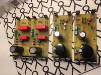
I have cleaned up my 4 psu's today (1 dual SSLV and two ReflectorD's), moved the diodes from being pcb-legs to "normal" mounted
.. The diodes don't get hot anyway, even with highish CCS.I think i can lower the CCS as pr. Salas instructions, so that i can have them all in same chassis as the DAC itself.
I meassured the current on the DAC's 3.3v line today, and it's only ~4mA when playing music (1mA when xmos is not connected), this Reflector was set at 350-400mA on this one, and i have lowered it to 50-100mA now!
The 5v line for the Xmos i meassured to ~120mA, and is set for ~250mA
I wrote DIYINHK today, asking them different and why they state that +12/-12 must be >100 for each channel, and why they state that the 3.3v line must be >300mA... makes no sense to me, being so conservative
Let's see theyre answer, they normally gives good answers, and they have a pretty good service i think.
Jesper.
Attachments
You could run all kinds of files with your new current limit settings and see in practice if there are any sneaky peak current demands. If no processing anomaly ever occurs and the SQ is always good, means the settings are rich enough.
Yes; i kindof allready did that...
The +/-12v lines are very steady both voltage and current (stable and stays at 30mA, also when play/pause some music) -The same goes for the 3.3v line, it settles at ~4mA and stays there. Well if it loose "lock" or whatever i did for teasing it so that it stops playing, the current falls down to 3,5mA.
All meassures are done both through some 0.1ohm's and with a DMM in serial uA / mA setting mode. Same approx. numbers as with resistors (I did this to make sure, i wasent fooled by my setup)
Good day.
Jesper.
Here's a building thread for the SSLV1.1 BiB PCB reg. Its to discuss builds, ask questions, tell stories.
*''Lazybutt'' Fred's Excel calc to help you configure has been added on 1/14/12
**The pdf guide on GoogleDocs
When and how to connect the reg in two wire mode

Dear Salas,
As you know the 2sk117GR/2sk170GR has been EOL right now,do you have any other part to replace this part in this shunt reg. You comments and suggestion will be great appreciate.
Best Regards
Leo
- Home
- Amplifiers
- Power Supplies
- SSLV1.1 builds & fairy tales