Hi Salas
I was finally able to finish populating my v1.1 board this evening.
I had to get creative in order to set R301 to 12 Ohms. I didn’t have much to speak of in higher wattage resistors. I managed to find some 47 Ohm 3 watt Panasonics and paralleled 4 to get where I needed to be.
The only caps with appropriate values I had for the lytics at 301 and 303 were the Silmics. At least I got them on sale at a good price.
Anyway...I gave the board a cleaning and started getting together the other bits I needed to try and test it.
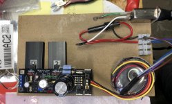
I temporarily attached some small heatsinks to the transistors. They will be bolted to an aluminum case ultimately. Will this be good enough for testing purposes?
I’ve got my Triad transformer wired up to an IEC with an inline slow blow 1 amp fuse in between. Should I wire the IEC earth reference to one of the SSLV boards standoff lugs?
The Triad has dual primaries and secondaries. It’s suppossed to put out 12V. I wired the primaries up parallel and got just short of 14V out of it.
I referred to the manual for the section on wiring the SSLV output with a dummy load.
This is where I need some help again. I don’t understand the formulas for calculating the resistor needed for this process.
You mentioned that setting R301 to 12 Ohms would allow the supply to deliver 250-300mA of current.
My target output voltage is 8V.
Also, should my pot in the voltage reference section be adjusted prior to powering the circuit up?
I was finally able to finish populating my v1.1 board this evening.
I had to get creative in order to set R301 to 12 Ohms. I didn’t have much to speak of in higher wattage resistors. I managed to find some 47 Ohm 3 watt Panasonics and paralleled 4 to get where I needed to be.
The only caps with appropriate values I had for the lytics at 301 and 303 were the Silmics. At least I got them on sale at a good price.
Anyway...I gave the board a cleaning and started getting together the other bits I needed to try and test it.
I temporarily attached some small heatsinks to the transistors. They will be bolted to an aluminum case ultimately. Will this be good enough for testing purposes?
I’ve got my Triad transformer wired up to an IEC with an inline slow blow 1 amp fuse in between. Should I wire the IEC earth reference to one of the SSLV boards standoff lugs?
The Triad has dual primaries and secondaries. It’s suppossed to put out 12V. I wired the primaries up parallel and got just short of 14V out of it.
I referred to the manual for the section on wiring the SSLV output with a dummy load.
This is where I need some help again. I don’t understand the formulas for calculating the resistor needed for this process.
You mentioned that setting R301 to 12 Ohms would allow the supply to deliver 250-300mA of current.
My target output voltage is 8V.
Also, should my pot in the voltage reference section be adjusted prior to powering the circuit up?
Attachments

Hi
Lets assume your real load in the end will be 150mA at 8V rail and you want to know beforehand if your reg set up can take it and how its dissipation is going to be. For also knowing if it works fine in all aspects, estimate its final appropriate size sinks or case etc.
So you do a dummy load test. The dummy test logic is simply Ohm's law. 8V/0.15A=53R. 8V*0.15A=1.2W. Thus a 47R 5W or two 100R 2W in parallel should be close enough for your telltale dummy load. Even a 47 Ohm 3W will do but it will get hotter than a 5W.
Your now sinks are small barely adequate for a quick test. Just watch their temperature. Stop when they will go over 100C. Especially the first one near the setting resistors is going to climb up fast. Because it will handle the Vdif (RawDC-Vout)*CCS dissipation. The other one will share power with the load because shunt.
Start with your voltage pot at 1/3 its full value. Have a voltmeter across the dummy and adjust your pot for 8V output rail. If you got another meter with a temperature probe have it monitoring the first sink. Don't rest the sinks or the dummy on an easy to burn surface. That (MDF?) board in the picture will do. Don't touch those sinks or the dummy resistor(s) for feeling the temperature.
To know what CCS current you achieved in practice because there are tolerances involved measure the voltage drop across your 4x47R parallel network and divide it by their R. If its say 3V/11.75R you got 0.255A. This info will come handy later on to reset R if the real load will need any more mA during TOC reading etc. Because your now info about that transport's consumption pattern seems vague.
Don't wire the mains protective earth to one of the board's stand offs. No use because they are isolated to the board's circuit anyway. Good luck.
Just wanted to say thanks for all your help again Salas.
I got my SSLV up and running after digging through about 6 boxes of parts and finally scoring some high wattage 100 Ohm resistors for the dummy load.
I also changed out the heatsinks to some bigger ones.
I brought it up slowly on my variac just in case something went wrong.
LEDs came on pretty quickly.
Once the output climbed up over 10V or so I tried adjusting the pot to bring it down...no response at the output...so I slowly brought the supply all the way to mains voltage which resulted in about 12V at the output and gave it another try.
Bingo!...I was able to easily dial it down to 8V at the output. Actually, I decided to see what the range was and easily got down below 5V.
I took some temp measurements at Q301 after about 10 minutes. I only had about 40 degrees C.
Measurement across R301 gave me about 2.95V. So you nailed it with the 250mA setting using 12 Ohms.
I did a cold start test this morning to see what the output voltage and current setting was like. It immediately came up right to where I want it.
So now I just need to figure out a way to secure things to a board temporarily so I can see what happens when I try powering the transport with it.
Attachments
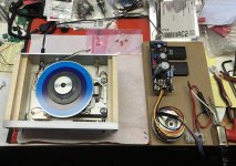
I took some time to test my CD Transport with the SSLV today.
To make things easier I wired the output of the SSLV for 2 wire mode.
That just allowed me to hook it up without having to change the power inlet and switch I already had installed in the transport chassis.
Unfortunately, things didn’t go well.
I’m back to the same exact symptoms that I had trying to run the transport on a 12V wallwort fed through the mosfet regulator which resulted in an 8V output when connected to the transport circuit.
While trying to read the TOC there are wild fluctuations in the voltage level measured going into the transport circuit.
When the TOC process is happening there is visual dimming of the red LEDs in the voltage reference section on the SSLV.
I didn’t even have the display or disc illuminating LEDs connected so they weren’t consuming any current.
It would not read the TOC of the disc I put in.
The disc I used had also been difficult to read with the wallwort/mosfet regulator setup until I went with a higher 15V wallwort which resulted in about 10.5V idle after the regulator when connected to the transport circuit.
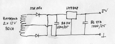
I’m sort of baffled by what is happening here. The power supply outlined in Peter Daniels thread documenting how he builds these Shigaclone transports is nothing special.
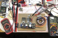
I’ve attached a circuit diagram he posted of the power supply he recommended along with my transport and SSLV on the bench as tested.
To make things easier I wired the output of the SSLV for 2 wire mode.
That just allowed me to hook it up without having to change the power inlet and switch I already had installed in the transport chassis.
Unfortunately, things didn’t go well.
I’m back to the same exact symptoms that I had trying to run the transport on a 12V wallwort fed through the mosfet regulator which resulted in an 8V output when connected to the transport circuit.
While trying to read the TOC there are wild fluctuations in the voltage level measured going into the transport circuit.
When the TOC process is happening there is visual dimming of the red LEDs in the voltage reference section on the SSLV.
I didn’t even have the display or disc illuminating LEDs connected so they weren’t consuming any current.
It would not read the TOC of the disc I put in.
The disc I used had also been difficult to read with the wallwort/mosfet regulator setup until I went with a higher 15V wallwort which resulted in about 10.5V idle after the regulator when connected to the transport circuit.
I’m sort of baffled by what is happening here. The power supply outlined in Peter Daniels thread documenting how he builds these Shigaclone transports is nothing special.
I’ve attached a circuit diagram he posted of the power supply he recommended along with my transport and SSLV on the bench as tested.
Attachments
Last edited:
I’m not sure if you mean voltage or current.
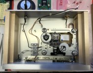
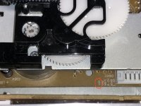
The voltage input is 8V and is labeled on the transport circuit board where the original power supply and other connections were made (see picture of my transport with the input voltage labeled that I circled in the picture of the board).
As far as how much current the circuit consumes, that appears to be a matter of conjecture. I came across some information in the original build thread that I posted here previously I think, but I’ve found no hard data on the subject yet.
Attachments
Current consumption at 8 volts regulated is up to 530mA at full sled swing to stop, 200mA when running and about 470mA when swinging through a disc searching.
http://https://www.diyaudio.com/forums/digital-source/120229-finally-affordable-cd-transport-shigaclone-story-post1920424.html
http://https://www.diyaudio.com/forums/digital-source/120229-finally-affordable-cd-transport-shigaclone-story-post1920424.html
Thanks Salas...I thought you might say that, but wanted confirmation.
I was trying to drill down into some of the related threads on building these transports. It seems like the power supplies evolved all over the place.
Ugh...now I have to try and make a high wattage 6 Ohm resistor from something in my bins.
I was trying to drill down into some of the related threads on building these transports. It seems like the power supplies evolved all over the place.
Ugh...now I have to try and make a high wattage 6 Ohm resistor from something in my bins.
Try again as I edited that link: https://www.diyaudio.com/forums/dig...ansport-shigaclone-story-360.html#post1920424
Hi Salas
I got tired of playing games trying to come up with low resistance high wattage resistors for the current setting.
I was able to find a place about 45 minutes away from where I live today that turned out to be like a classic Radio Shack on steroids.
They didn’t carry any of the Dale , Panasonic etc stuff you can get from Mouser or Digi-Key. It was a lot of NTE stuff.
I got what I needed...actually more than I should have. They had a lot of neat aerospace connectors amongst other things.
Anyway...the SSLV is up and running with a 4.7Ohm 5 Watt wirewound setting current.
I get the same measurement across the current setter with my 50 Ohm dummy load as I do when it’s actually hooked up to the transport...about 2.5V.
Doing the math as you demonstrated... with 4.7 Ohms that gives me about 530mA.
The transport fired right up and went through its TOC process. I didn’t see any fluctuations in the voltage measured going into the circuit. However, I hadn’t loaded a disc for it to try and read yet.
When I loaded a disc and initiated the TOC process it was able to read the disc and complete the process without any issues I noticed. It also initiated play properly.
When I ran it through the process a second time I noticed that the red LEDs in the voltage reference section were more like flashing than dimming overall.
I did the TOC process a few more times and noticed that now that the transport was actually reading the disc there were fluctuations in the voltage I was measuring going into the circuit.
It wasn’t as bad as I had seen previously, but it was still dipping down to below 6V.
There doesn’t seem to be too much heat soaking of the transistors or current setting resistor even with the moderate heatsinks I’m testing with. I played several tracks on a disc and measured temps approaching 60 degrees C on the resistor and the metal flange of Q301...Q306 was slightly cooler.
So now the question is whether or not I should up the current setting given the flashing of the LEDs and the drop in voltage I’m seeing going into the circuit even though the transport appears to function?
If so, do I jump to about 2.2 or 2.4 Ohms?
I’m wondering how the heat sinking requirements will pan out.
Also...not sure how many more successful soldering sessions the pads will take on the board for the current setting resistor.
Hi, doing progress I see. Seems you're near. Solder a 47 Ohm across that 4.7 to give it a little bit more current space to see what happens before attempting a jump to much more current space. In an effort to hit the just enough constant current threshold and keep excess dissipation at bay.
If still not enough for no occasional blinks and voltage drops, trying 3.9R would be the next closer step.
If still not enough for no occasional blinks and voltage drops, trying 3.9R would be the next closer step.
- Home
- Amplifiers
- Power Supplies
- SSLV1.1 builds & fairy tales