Hi Guys,
I've built a P3A using Rod's boards, standard parts etc.
https://sound-au.com/project3a.htm

+/- 34Vdc rails
2SA1973/2SC5200 output transistors
KSA1220/KSC2690 drivers and Q4
BC546 Q1,2,3 and Q9.
The right channel is behaving normally.
The left channel isn't.
My dummy load is 4x 16R 100w resistors in parallel for 4.3R as per my DMM.
My scope is a Instrustar ISDS205B cheap and nasty USB jobbie.
My first test on the problematic left channel had 3Vrms on the output of the amp. After something like 30-60s the 3A fuses on the supply rails blew.
And the heatsink was pretty darn warm.
The 2nd test was going ok, same signal, same 3Vrms on the ouput, the supply rail fuses didnt blow. After probably 60s I saw a little puff of smoke come from somewhere around Q6/Q9. I didn't see any damage, I think it was the cable tie coupling q6 and q9 together beginning to melt.
After this I learned that I can only do short bursts of testing if I dont want to start replacing transistors.
I performed a few more short tests and took some screen shots to digest whats going on.
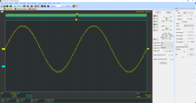
Right side 1kHz sine wave
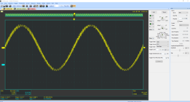
Left side 1kHz sine wave.
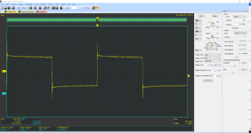
Right side 1kHz square wave.
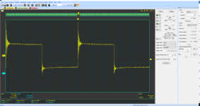
Left side 1kHz square wave.
There was also another square wave test on the left side that I did not get a screen shot of, that looked like this.
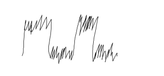
Forgive my crude MS Paint work. With my limited understanding this would be full scale oscillation.
This was a purely resistive 4R load, no capacitance in parallel.
So if I am not imagining things, I have a rather unstable amplifier that needs some love to get happy.
My first step is going to be to remove the board from the heatsink and give it a damn thorough eyeball to check for any mistakes, bad joints etc.
Assuming I don't find any construction errors, it seems to me that the next step would be to perform the same square wave test and do some probing around to see if I can find where the oscillation starts.
I've built a P3A using Rod's boards, standard parts etc.
https://sound-au.com/project3a.htm
+/- 34Vdc rails
2SA1973/2SC5200 output transistors
KSA1220/KSC2690 drivers and Q4
BC546 Q1,2,3 and Q9.
The right channel is behaving normally.
The left channel isn't.
My dummy load is 4x 16R 100w resistors in parallel for 4.3R as per my DMM.
My scope is a Instrustar ISDS205B cheap and nasty USB jobbie.
My first test on the problematic left channel had 3Vrms on the output of the amp. After something like 30-60s the 3A fuses on the supply rails blew.
And the heatsink was pretty darn warm.
The 2nd test was going ok, same signal, same 3Vrms on the ouput, the supply rail fuses didnt blow. After probably 60s I saw a little puff of smoke come from somewhere around Q6/Q9. I didn't see any damage, I think it was the cable tie coupling q6 and q9 together beginning to melt.
After this I learned that I can only do short bursts of testing if I dont want to start replacing transistors.
I performed a few more short tests and took some screen shots to digest whats going on.

Right side 1kHz sine wave

Left side 1kHz sine wave.

Right side 1kHz square wave.

Left side 1kHz square wave.
There was also another square wave test on the left side that I did not get a screen shot of, that looked like this.

Forgive my crude MS Paint work. With my limited understanding this would be full scale oscillation.
This was a purely resistive 4R load, no capacitance in parallel.
So if I am not imagining things, I have a rather unstable amplifier that needs some love to get happy.
My first step is going to be to remove the board from the heatsink and give it a damn thorough eyeball to check for any mistakes, bad joints etc.
Assuming I don't find any construction errors, it seems to me that the next step would be to perform the same square wave test and do some probing around to see if I can find where the oscillation starts.
Attachments
It does sound like oscillation, but at the same time, your waveforms don't show large amplitude effects that I would expect in order to blow rail fuses. Kind of looks more like it's picking up external HF interference.
Check C6,C7 and R15.
That input filter is totally inadequate in my view. You could try increasing C2 to 470pF or even 1nF.
Check C6,C7 and R15.
That input filter is totally inadequate in my view. You could try increasing C2 to 470pF or even 1nF.
Last edited by a moderator:
Nope. It works perfectly in my case.That input filter is totally inadequate in my view
H
HAYK
What made you decide to use ksa1220 ksc2690 ?
From where did you obtain?
Add 100nF across the C_E of Q9.
From where did you obtain?
Add 100nF across the C_E of Q9.
I read somewhere around here that ksa1220 ksc2690 is a good driver combination with the 1943/5200.
All the transisters were purchased from either mouser or farnel, can't remember which.
All the transisters were purchased from either mouser or farnel, can't remember which.
This evening I have had time to pull the problematic left board off of the heatsink, check everything is correct and look for bad joints etc.
No bad joints, solder bridges and all of the transistors are orientated correctly and identically to the working right channel.
So having ruled out the easy option of fixing an error, it looks like I need to put it all back together and start poking around with the scope to see which transistor is unhappy.
If I was to try and infer things from those scope shots, I noticed that the positive going side of the square wave on the problem channel is ringing with a much higher amplitude than the negative going side of the square wave.
This would suggest to me that the positive side is the first place to look: the collector of Q7, emitter of q5, perhaps collector of q4 too.
Is there any merit to this deduction or was mummy lying when she told me how smart I was?
The right channel is behaving normally.
The left channel isn't.
both channels are poor.
there should be no overshoot evident at 10KHz, let alone 1KHz
have you built this amp? how is your response to a 10KHz squarewave?Nope. It works perfectly in my case.
yes
Yes. Good.have you built this amp? how is your response to a 10KHz squarewave?
Attachments
Well, I think I've really done it now.
I was finally allowed some time to do some more testing.
I put a probe on the collectors of the output transistors Q7 and Q8
Turned it on, connected the sig gen and in the time it took me to try and range the scope I had smoke coming out of what appears to be q9.
While panicking to remove the signal I saw the 3A positive rail fuse blow.
2 more attempts at testing and the same positive rail fuse blew again both times.
Seems to me that I have fried either q9 or q6 or both.
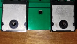
These are the output transistors which appear to have gotten very hot!
You can see that they have gotten hot enough for the metal to deform into the surface texture of the silpads.
Also if I am not mistake you can see the outline of the internal structure which I certainly cannot see on the unused output transistors in my stash.
I was finally allowed some time to do some more testing.
I put a probe on the collectors of the output transistors Q7 and Q8
Turned it on, connected the sig gen and in the time it took me to try and range the scope I had smoke coming out of what appears to be q9.
While panicking to remove the signal I saw the 3A positive rail fuse blow.
2 more attempts at testing and the same positive rail fuse blew again both times.
Seems to me that I have fried either q9 or q6 or both.

These are the output transistors which appear to have gotten very hot!
You can see that they have gotten hot enough for the metal to deform into the surface texture of the silpads.
Also if I am not mistake you can see the outline of the internal structure which I certainly cannot see on the unused output transistors in my stash.
They were from mouser.
The pair on the other channel look normal. These ones just got far too hot me thinks.
The pair on the other channel look normal. These ones just got far too hot me thinks.
H
HAYK
A transistor gets destroyed at 150°C. No chance the metal can get altered at this temperature. Check if the backplates are flat. If not, they are counterfeit.
How would I check for flatness?
They are definately rough to the touch in the area that looks likes it has a silpad texture to it.
Is it possible to get counterfeit transistors from mouser?
They are definately rough to the touch in the area that looks likes it has a silpad texture to it.
Is it possible to get counterfeit transistors from mouser?
H
HAYK
Put the two transistors back to back and look the light that passes through. If not flat you will see the curvature. I have about 10 pair of these, the backplates are shining like chrome.
If the transistors went hot enough to destroy themselves, they certainly exceeded 200~250°C, enough to melt the matte tin finish of the tabs.
Have a very close look at C4, maybe C6, and to avoid further casualties operate the amplifier at ~half-voltage during debugging, and maybe insert two 10ohm resistors in the supply lines: with the local bypass, operation shouldn't be affected for low output power levels
Have a very close look at C4, maybe C6, and to avoid further casualties operate the amplifier at ~half-voltage during debugging, and maybe insert two 10ohm resistors in the supply lines: with the local bypass, operation shouldn't be affected for low output power levels
Well, a bit more testing.
Q9 gives continuity on my DMM across all combinations of terminals which I believe means it is shorted?
Also the leg for the emitter is wobbly.
Q6 gives no continuity across any combination of ferminals which I believe means failed open?
C4 and c6 look ok. I don't have a method to measure the capacitance on a 100pF capacitor. It doesnt look damanged. I used CDM silver mica in both positions.
My iron is heating up to remove Q7/Q8 for examination.
With my DMM on diode test or continuity mode, whatever you like to call it
the 2SA1943 behaves the following:
B to E = OL
E to B = 0.54
B to C = OL
C to B = 0.55
E to C = OL
C to E = OL
A fresh 2SA1943 gives
B to E = OL
E to B = 0.69
B to C = OL
C to B = 0.6
E to C = OL
C to E = OL
The 2SC5200:
B to E = 0.03
E to B = 0.01
B to C = 0.45
C to B = OL
E to C = OL
C to E = 0.045
A fresh 2SC5200 gives
B to E = 0.539
E to B = OL
B to C = 0.53
C to B = OL
E to C = OL
C to E = OL
So it appears to me that I have a fried 2SC5200 but the 2SA1943 has survived.
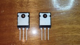
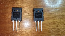
All of the 1943 and the 5200 chips I have let through a silver of light when held back to back up to a light, just a hair.
The brand new ones have what I would call a dull surface on the back.
All the transistors were purchased from Mouser back in December 2019.


- Home
- Amplifiers
- Solid State
- Stability testing my new Rod Elliot P3A


