You may also want to use a light bulb current limiter when testing. This should prevent the outputs from drawing too much current.
Take a look at figure 1C and the accompanying text here from Rod's article on square wave testing amplifiers and filters. The hand drawn diagram you posted pretty much matches it...
Also, from Rod's notes, have you got VR1 set to maximum on both channels? He says:
Are you sure about the compatibility of the transistors? I'd been considering building P3a but couldn't work out what I should be using given that almost everything is EOL or unobtanium with the possible exceptions of the NJW3281 (Digikey have it in stock) and NJW1302 (still active but out of stock). Mouser claim to have more stock of 3281 on April fools day 2024 🙂 There's also a guy on EBay who claims to be selling matched sets of 8... Is it worth waiting and trying it with bd140&bd139, bc546 and those two output transistors when the 1302 is available?
Also, from Rod's notes, have you got VR1 set to maximum on both channels? He says:
Before applying power, make sure that VR1 is set to maximum resistance to get minimum quiescent current. This is very important, as if set to minimum resistance, the quiescent current will be very high indeed (almost certainly enough to blow the output transistors!).
Are you sure about the compatibility of the transistors? I'd been considering building P3a but couldn't work out what I should be using given that almost everything is EOL or unobtanium with the possible exceptions of the NJW3281 (Digikey have it in stock) and NJW1302 (still active but out of stock). Mouser claim to have more stock of 3281 on April fools day 2024 🙂 There's also a guy on EBay who claims to be selling matched sets of 8... Is it worth waiting and trying it with bd140&bd139, bc546 and those two output transistors when the 1302 is available?
A few thoughts:
Regarding square waves, need to monitor how square waves look going into an amplifier as compared to how the coming out. Some fast rise-time signal generators will ring if not properly terminated at the end of the cable. May make no difference whether its 1kHz or 10kHz, the rise time may be the same for both.
Also, common to disable bias spreaders at first test, and bring unit up slowly on a variac while watching the outputs with a scope. No load is needed for first tests, so variac can be low power.
Also, what does the layout look like for this amplifier? Is there there stray coupling between inputs and outputs or other areas that might be of concern?
I didn't have any issues with the initial turn on or biasing.
I followed the test procedure laid out in the p3a article.
Bias was set at 75ma.
The amp played music normally when connected to my test speakers. It even made my test speakers sound surprisingly good.
It was only when I started testing on the scope that the issues started.
Perhaps I was unwise to test into a 4 ohm load? My speakers are 4ohm so this seemed like a good idea.
What is the capacitance of the scope probes? Are they causing phase shift as some high impedance part of the circuit.
Do the scope probe grounds create ground loops that affect stability?
Only point is that if worked normally up to a certain point, then you changed something and a problem started at the same time, that's rather suspicious. Could be a coincidence, but maybe not.
Do the scope probe grounds create ground loops that affect stability?
Only point is that if worked normally up to a certain point, then you changed something and a problem started at the same time, that's rather suspicious. Could be a coincidence, but maybe not.

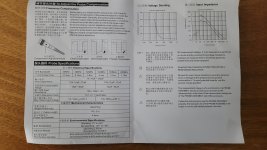
Here's the specs for the probes.
My deduction would be that since one channel is working and one is not that it wouldn't be an issue with the probes since it should cause the same issue on both channels?
The first test I did with the scope was a plain 1kHz sine wave at 2.3Vrms into 4ohm.
The left channel blew both rail fuses, the right channel was fine.
Are the layouts, wiring, etc., exactly identical for both channels? Grounding the same? Can you hi-res post pics so we can get an idea?
Did you replace the suspected bad 2SC5200?
Do you have a way of bringing it up gradually such as with a variac, with no output load and with bias spreader shorted out? The idea would be to take some measurements with no input signal and no load. Just measure voltage drops across some resistors to verify bias currents look reasonable, while watching temperature and the output with scope. IOW, be very gentle and do some simple checks. If everything looks okay then maybe introduce some test signals, sine waves to start with and look for any trouble there. If that goes okay the try low level square waves. Check for ringing on square wave edges at the input. If its ringing at the input try putting a 50R termination load there for the generator. Also turn up the scope sweep rate so ringing waveform is clearly visible. Count the number of rings if you can. Compare that to the number of rings at the output. Best to use one probe at the input and one at the output for easy comparison. Make sure the probes are set to 10x mode. Ground probes as close as possible to the measurement point. If not super familiar with probing techniques, always good to refresh with https://www.tek.com/en/documents/whitepaper/abcs-probes-primer The section on Advanced Probing Techniques and Grounding is very good.
Anyway, the goal is to get some readings without damaging anything. Also compare readings of both channels for comparison. See if there is any evidence of what might be the problem. Also see if there are tests to help isolate the problem to a local part of the circuitry.
That sort of thing would be my suggestion anyway.
Does the amp have an output inductor? If not it might not tolerate capacitive loads such as a probe on its x1 setting, leading to destructive oscillation.
Always use a 'scope x10 probe in the x10 setting, never x1 (unless you really have a good reason to and understand the limitations, such as much lower bandwidth and heavy capacitive loading).
Always first test an amp with no load or light load (1k?), and with current limited supplies (such as a adding 100 ohm power resistor in line with each supply rail, between the main filter caps and the amp). A dim bulb tester won't stop the filter caps dumping 100A+ into a short circuit, Current limiting resistors will, which can mitigate any cascade failure.
Only if no tendancy to oscillate is shown upto full swing is it wise to remove the current limiting or adding a heavier load. Monitor the supply current during testing - any discontinuous unexpected changes in current may be oscillation breaking out. Slow but inexorable increase could indicate that thermal compensation isn't adequate.
BTW expect stability issues if under-biased, so first ensure a reasonable bias point with no input or output load, then look for oscillation.
Careful about testing high frequencies at full swing - 20+kHz full swing square wave for instance may cook the Zobel network - the amp designer wasn't allowing for that as it would destroy your tweeters first.
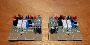
The layout of the 2 boards is slightly different in the routing of the power rails. Otherwise Identical.

The wiring from the psu to the faulty left channel is slightly longer in this test bed than the right side.
I could show a photo of the pcb traces but this would go against the request of Rod not to disclose his IP so I will avoid it if I can.
The difference is that one channel has the power rail traces running left to right, the other channel power rail traces right to left.

I have chosen to cut the two boards in half (which is provided for in the design) so that I can mount them on separate heatsinks when I get it out of my test rig and into the chassis proper.
I haven't yet replaced any transistors as due to my darling toddler, I get limited time on a daily basis to work at my desk.
I think I should remove Q4 and q6 for testing also before replacing anything.

The wiring from the psu to the faulty left channel is slightly longer in this test bed than the right side.
I could show a photo of the pcb traces but this would go against the request of Rod not to disclose his IP so I will avoid it if I can.
The difference is that one channel has the power rail traces running left to right, the other channel power rail traces right to left.

I have chosen to cut the two boards in half (which is provided for in the design) so that I can mount them on separate heatsinks when I get it out of my test rig and into the chassis proper.
I haven't yet replaced any transistors as due to my darling toddler, I get limited time on a daily basis to work at my desk.
I think I should remove Q4 and q6 for testing also before replacing anything.
I'm surprised nobody has either simulated or benched a exploration of exactly what the nested loop of the CFP is ?
Then one could integrate a proper compensation network to give the same "rock solid" stability as a EF2/3.
I've never used it , but a CFP is natively fast and can have a current gain somewhere between a EF2 and 3.
If you could tame that local (driver-output) FB loop , no special layout or devices would be necessary (NO stability issues).
Ha ! If he fixed the CFP or used a EF , there would be no need for "Rod's IP".
Edit - maybe that was the plan all along ?
OS
Such an exploration is beyond my capabilities but if somebody else is interested I would be glad to follow along in their footsteps
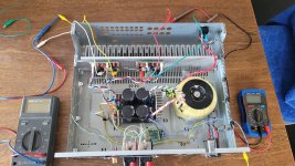
Is there a schematic for the power supply, and the other little board? Is there an overall interconnection wiring diagram that includes where all grounds are physically connected? Also, in the picture, can you confirm which is electrically the left and right channel?
In addition, it looks like there is some randomly routed I/O wiring. Just poking some of that stuff around might show some symptoms. Hard to say exactly from looking at the pic.
In addition, it looks like there is some randomly routed I/O wiring. Just poking some of that stuff around might show some symptoms. Hard to say exactly from looking at the pic.
Last edited:
Reducing the loop gain of the whole amp (LTP Re) would help , but does not address the primary issue (CFP).Vbe multipler should be bypassed with .1uf ceramic cap. Also input transistors should be degenerated with 100 ohm resistors.
In simulations (not tested in real life) I’ve found 10r to 22r of emitter degeneration on the drivers helps a lot with stability. Observed by elimination of ringing on square wave response.
Of course its possible to slow it down, degenerate, etc., but isn't the thing supposed to be proven working design? If so, there is likely something wrong with the particular implementation. Substitute parts, layout, grounding, etc.
According to the designer , only his careful layout will entail good results (IP).but isn't the thing supposed to be proven working design?
This why I avoided it (P3A) in 2008 and went the Badger/Wolverine route. NO ONE ever has
any of these issues with any of my designs. They work with sloppy layouts and junkbox semi's.
Hint - original P3A used outputs that had a lower Ft than what the oscillation freq. is....
OS
Yes ! add some Local PS decoupling .too.In simulations (not tested in real life) I’ve found 10r to 22r of emitter degeneration on the drivers helps a lot with stability. Observed by elimination of ringing on square wave response.
I'm going to try to probe (Bode graph) just the output stage in isolation
- Home
- Amplifiers
- Solid State
- Stability testing my new Rod Elliot P3A