One issue you may have if the circuit is powered by a single 9V battery is that large boost at 220Hz eating all your headroom and causing clipping. If possible I'd use two batteries in series for 18V supply. And of course if you want reasonable battery life, low power opamps, given the number of them you need. I'd probably go with a couple of quad TLE2064 and one dual TLE2062, which will also handle well the heavy loads in some parts of the circuit. Then use 50k trimmers instead of pots and the pcb will be as compact as it can be, while still being adjustable in case it needs fine-tuning later.
Also the circuit as shown has an input impedance of 2k2 but active pickups like to see a 25k or so load, you can simply replace the input resistor (R20) and the feedback one of the last opamp (R41) with 22k or whatever you need if the pickups are connected directly to the eq.
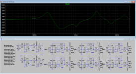
Finally, when calculating the bandpass filters I specified E12 caps and E96 resistors for better precision, but it's likely that E6 / E24 will be enough for this. Again, it would be nice to see the actual frequency response they are expecting.
Also the circuit as shown has an input impedance of 2k2 but active pickups like to see a 25k or so load, you can simply replace the input resistor (R20) and the feedback one of the last opamp (R41) with 22k or whatever you need if the pickups are connected directly to the eq.
Finally, when calculating the bandpass filters I specified E12 caps and E96 resistors for better precision, but it's likely that E6 / E24 will be enough for this. Again, it would be nice to see the actual frequency response they are expecting.

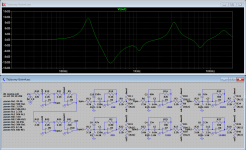
In LTSpice, nodes with the same label are all connected together.
Some things don't look right in the plot, e.g. the 430Hz band seems to be the one with the lowest Q and it's supposed to be the highest at 1.5, the 1080Hz cut clearly has a higher Q than 0.3... Please double check...
Some things don't look right in the plot, e.g. the 430Hz band seems to be the one with the lowest Q and it's supposed to be the highest at 1.5, the 1080Hz cut clearly has a higher Q than 0.3... Please double check...

- Home
- Design & Build
- Electronic Design
- Strange EQ design