Yes, if it is sensitive to output cables/load, the coil/resistor output network may work, but it may end up being too large if the instability is bad.
There is a possibility that the VAS is oscillating by itself without causing problems for the other stages, but of course it could be transmitting AM modulated radio waves so every ham in the area knows what you listen to...
There is a possibility that the VAS is oscillating by itself without causing problems for the other stages, but of course it could be transmitting AM modulated radio waves so every ham in the area knows what you listen to...
The Bushe coil is placed not because of the wires, but because of the capacitive nature of the acoustic system impedance.Yes, if it is sensitive to output cables/load, the coil/resistor output network may work,
And the Bushe coil has nothing to do with the radio frequency range, on the contrary, it protects the NFB circuit from interference.
Hello Mr.Miles and other diy members, after long time i play SR55 amplifier, i face a problem with my DC offset. When I Power on SR55 then DC offset between 70-150mv, after sometime (2-3) it's settled on +/-1 mv. How to solve this problem please suggest.
One more thing can somebody tell me how to check clipping without oscilloscope and clipping circuit. Because I use some different signal input sources like phones, ipod, Bluetooth modules and desktop pc. With PC signal I set volume 50% and 1khz with tone generator I got .6-7mv AC on amplifier input and on speaker terminal I got 24-26v Ac.
According ohm law
P=V²/R That's means
P=24²/8
P=72w
I use 42volt Dc and it means amplifier clipping on 28-29V with clipping circuit (15v zener).
With 28V amplifier power 98w. My next Question is what is the output power of SR55.
Mr.Miles and members I have no deep knowledge about electronic just hobby. Therefore we also need your help on clipping topic.
Regards
Attachments
Replace R4 use 56k instead 120k...Hello Mr.Miles and other diy members, after long time i play SR55 amplifier, i face a problem with my DC offset. When I Power on SR55 then DC offset between 70-150mv, after sometime (2-3) it's settled on +/-1 mv. How to solve this problem please suggest.

One more thing can somebody tell me how to check clipping without oscilloscope and clipping circuit.
Try this:
1/ You need to play a pure sine test tone in the 400 to 1kHz range. Nothing else will do for this. It has to be a pure tone. A decent MP3 file is fine.
2/ Connect a dummy load to the amp (it is up to you to make sure the amp has adequate heatsinks etc). You can try without a dummy load at first.
3/ Connect a speaker in series with 2 watt resistor in the 390 to 680 ohm range (it's not critical) and place this additional load across the dummy load (the speaker terminals).
4/ As you turn the volume up the tone from the speaker should sound really pure. As you reach clipping it will suddenly change to a harsher note. The resistor means the speaker will only see a very small voltage but the tone should be clearly heard.
Do the test quickly at high volumes to avoid overheating the amp. If you measure the AC voltage across the dummy load at the point clipping occurs, you can calculate the power.
Replace R4 use 56k instead 120k...
FirstTry this:
1/ You need to play a pure sine test tone in the 400 to 1kHz range. Nothing else will do for this. It has to be a pure tone. A decent MP3 file is fine.
2/ Connect a dummy load to the amp (it is up to you to make sure the amp has adequate heatsinks etc). You can try without a dummy load at first.
3/ Connect a speaker in series with 2 watt resistor in the 390 to 680 ohm range (it's not critical) and place this additional load across the dummy load (the speaker terminals).
4/ As you turn the volume up the tone from the speaker should sound really pure. As you reach clipping it will suddenly change to a harsher note. The resistor means the speaker will only see a very small voltage but the tone should be clearly heard.
Do the test quickly at high volumes to avoid overheating the amp. If you measure the AC voltage across the dummy load at the point clipping occurs, you can calculate the power.
Thanks Mr.Miles for help on DC offset issue.Your suggestion 56k in instead 120k but I use 68k and problem solved.
Second, now about Peak wattage
I gave 1khz signal from pc and got 28-29 volt(ac) with 8ohm load. Is that okay?
Here i forget one thing, BF420-421 on available in my area so I use C2383 A1013. These changes gave any advantage or disadvantage.
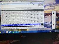
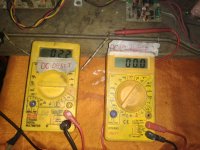
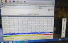
I post some pics also
1 pic without signal
2 pic with signal and in
3 pic 1khz with pc volume level ( i don't know who much mil volts or volt on signal)
Whats your opinion.....
Regards
Attachments
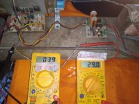
Assuming a sine wave then you have ~ 100 watts rms into 8 ohm.I gave 1khz signal from pc and got 28-29 volt(ac) with 8ohm load.
I remember using those BF devices video output transistors back in the day. You need to see what Apex says as to the suitability of the 2SC/2SA's as I haven't studied the design in detail.Here i forget one thing, BF420-421 on available in my area so I use C2383 A1013. These changes gave any advantage or disadvantage.
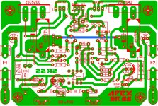
I'm currently pre-finishing a Q17 with mosfets, but if the gerber files were available I'd definitely go for it, ...SR200
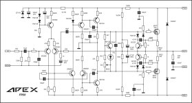
My new Project......
Greetings to everyone, especially to Mr. Mile for sharing such a beautiful projects.
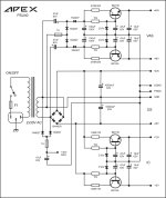
I would build an FR50 and as far as I can see hardly anyone makes amps with a separate regulated power supply for VAS. I would ask Mr. Mile or another expert is there any change on the schematic to use it with the PSU40 or just remove the 100R resistors. Thanks in advance
Has anyone else built FR50? Only OLAFK shared his impressions if I'm not mistaken...
Attachments
Last edited:
Greetings to everyone, especially Mr. Mile for his wonderful projects. The other day I assembled an SR200 amplifier, but I could not set the quiescent current, please tell what could be the matter?
Thank you in advance. (Sorry for my English.)
Thank you in advance. (Sorry for my English.)
Attachments
Last edited:
pictures or your actual build will be the first place to start. Did you make any changes to the schematics, make any replacements to the suggested transistors?
I ask, because the schematic is known to work, with numerous people having posted their working builds. So something is incorrect (either a part, or installed incorrectly) on your specific build.
I ask, because the schematic is known to work, with numerous people having posted their working builds. So something is incorrect (either a part, or installed incorrectly) on your specific build.
I did not make any changes to the printed circuit board. All components are installed according to the diagram. But there is no 2.3VDC voltage between the MJE350 collector and the MJE340 collector, measurements at these points show 1.2VDC.( sorry for my English )
Attachments
- Home
- Amplifiers
- Solid State
- Studio Reference Amplifier