
What is it that you don't like about the waveforms that you see with the battery on the high-side?
I'll try to explain. With no battery hooked up to any drivers, the inputs all look the same as in picture on post #14.
The driver depicted in post #15 is different than the other three. If I hook the battery to the high-side cap of it, all the inputs change and look like the second pic in #15. Only like 180 out of phase if that makes sense. All of the inputs change with just the battery on the one driver.
The driver depicted in post #15 is different than the other three. If I hook the battery to the high-side cap of it, all the inputs change and look like the second pic in #15. Only like 180 out of phase if that makes sense. All of the inputs change with just the battery on the one driver.
Could you have a solder bridge somewhere?
You can't tell phase with only one input to the scope. The pulse width changes which unexpected. It's like something in the high-side drive is leaking/shorted to the feedback loop.
You can't tell phase with only one input to the scope. The pulse width changes which unexpected. It's like something in the high-side drive is leaking/shorted to the feedback loop.
I was very careful. I can pull the driver board again and go over it.
I understand that on phase. Poor choice of words. The pulse width was opposite from the input to the drive side. Tried to post new pic. Not uploading once again.
Do the other three look correct? I tried a couple outputs on one of those. Still glowing bright.
I understand that on phase. Poor choice of words. The pulse width was opposite from the input to the drive side. Tried to post new pic. Not uploading once again.
Do the other three look correct? I tried a couple outputs on one of those. Still glowing bright.
I don't see any obvious overlap of the signals and they're nice and square so I don't see a problem there.
The fact that one IC produces a different result does seem like a problem.
The fact that one IC produces a different result does seem like a problem.
I've got the board out going over it again. I'm 65 and turn 66 tomorrow so my eye sight isn't what it once was but I use magnifiers to check it. I'll let you know.
Walmart has them for about $20 (pharmacy section). It's the best small lighted magnifier that I've ever found.
I don't see anything. I did an ohm check between legs of the chip. Nothing shorted. All I changed on the board was the drivers and one diode.
Do you think I should change the driver chip again?
Should one of the other output sections work even though that one doesn't look right?
Do you think I should change the driver chip again?
Should one of the other output sections work even though that one doesn't look right?
Another day. Another try. Checked the output driver board. Did not find any bridged joints. Removed the driver giving the erroneous wave forms on the high and low-side drives. Installed the driver board. Checked all inputs. Looked good. Checked the low-side drives. All looked good. Checked the high-side drives. All looked good. Put a pair of outputs only in the amp. The amp powered up and bulb did not burn bright. Did not have sound so I powered it down. Tried it a second time and the bulb glows bright. Any ideas?
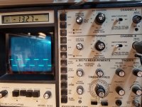
First pic is input signals. Next two high and low drive.
First pic is input signals. Next two high and low drive.
Attachments


Does the rail voltage build well before the amp starts to oscillate as is seen in the following clip?
http://www.bcae1.com/temp/ampstartup01.mkv
http://www.bcae1.com/temp/ampstartup01.mkv
- Home
- General Interest
- Car Audio
- Sundown SCV-7500.1