Note that if you use a standard choke like 195T, you will need two for one channel for balanced (bridged) operation. And if the inductors don’t share a common core, it’s not a SuSyLu anymore but simply a BTL LuFo (which still is very good as it gets you the same power, just not as low distortion).
If anyone is brave enough, removing the small magnet wire secondary on a MOT and replacing it with your own 14ga magnet wire for a double inductor with common core might be a DIY project. Better yet, remove all wires and rewind both as bifilar (double strand) and this ensures they have identical inductance and DCR. It’s work to wind 14ga wire though.
If anyone is brave enough, removing the small magnet wire secondary on a MOT and replacing it with your own 14ga magnet wire for a double inductor with common core might be a DIY project. Better yet, remove all wires and rewind both as bifilar (double strand) and this ensures they have identical inductance and DCR. It’s work to wind 14ga wire though.
This is certainly true, and I was speaking more to the use of chokes in the straight LuFo circuit. The SuSyLu really seems to require a custom wound bifilar choke for best performance, and this may be prohibitively expensive for many DIY builders.Note that if you use a standard choke like 195T, you will need two for one channel for balanced (bridged) operation. And if the inductors don’t share a common core, it’s not a SuSyLu anymore but simply a BTL LuFo (which still is very good as it gets you the same power, just not as low distortion).
try lundahl too he just make balanced choke for tube filamentI have asked Brian Sowter if they could make a balanced choke for the SuSyLu, and he seemed quite positive. But no firm quotes or stuff yet.
Which core size would be right for a SuSyLu balanced choke?
CUSTOM OUTPUT TRANSFORMERS
(Scroll down to see the table/list)
CUSTOM OUTPUT TRANSFORMERS
(Scroll down to see the table/list)
Which core size would be right for a SuSyLu balanced choke?
CUSTOM OUTPUT TRANSFORMERS
(Scroll down to see the table/list)
Looks like the 100w push pull would be the one. I assume these are bifilar then? About 7kg for 100w at 20Hz.
try lundahl too he just make balanced choke for tube filament
Lundahl said they won't make custom chokes in small numbers.
I am looking at the LL273/3.5A, which might be interesting for the SuSyLu, although it may not be enough iron at 2.5 kg only. Lundahl specified the series inductance of both windings in series at 95 mH, so each winding is 47 mH. However, they don't say at which frequency they specified the inductance value (I asked them).
Looks like the 100w push pull would be the one. I assume these are bifilar then? About 7kg for 100w at 20Hz.
Hmm, how did you determine the 100 W spec? As I understand the SuSyLu, the balanced choke does not transfer 100 W from one winding to the other -- or does it?
X, what are the weight and dimensions of your custom made choke? That might provide some clues of how "big" I need to go.
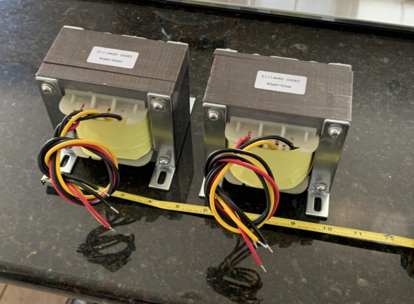
I think we discussed this - depends on how much magnetic energy storage you want for headroom. The custom dual balanced 600VA class EI core choke I have is 11lbs 5oz. The size and weight comes mostly from requirement of 14ga wire and 60mH with 0.5ohm DCR.
SuSyLu Where Are You?
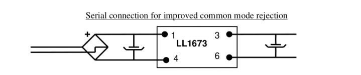
Impedance sweep (two separate ones line up) and fairly linear behavior from 20Hz to 20kHz.
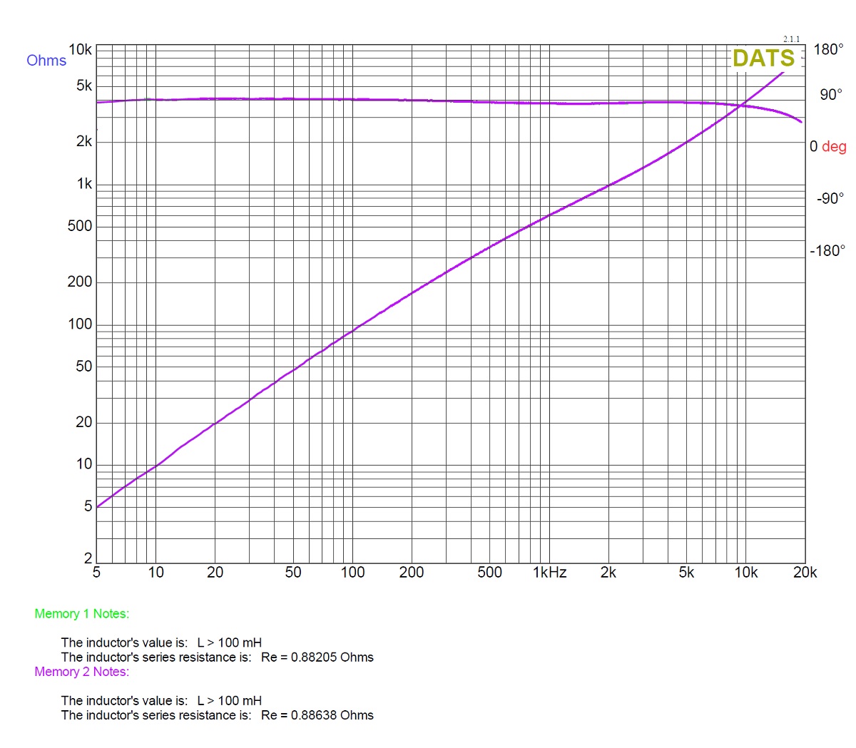
I am told that the 60mH and DCR spec of 0.5ohms is at 10kHz.
SuSyLu Where Are You?
Impedance sweep (two separate ones line up) and fairly linear behavior from 20Hz to 20kHz.
I am told that the 60mH and DCR spec of 0.5ohms is at 10kHz.
Last edited:
mbrennwa, with both winding in series being 95 mH, each winding is 24 mH, not 47 mH.
Oups, yes, you're right. I forgot that series or parallel windings act different when they're on the same core. I guess the Lundahl is out.
Last edited:

Here is something similar based on lu1014d and bifilar choke, including input stage, going back decade.
DIY Class-A amplifier - The Paper Horn by Inlow Sound
I wonder if anyone here has built it.
DIY Class-A amplifier - The Paper Horn by Inlow Sound
I wonder if anyone here has built it.
It looks just like Susan Parker’s Zeus amp but without transformer coupled output. I guess as they say about most things in audio, “there’s really nothing new under the sun.”
Gilson’s Balanced Source Follower Amp (1978):

Susan Parker’s Zeus (1994):

John Inlow’s all MOSFET cascoded balanced drive (2009):
Gilson’s Balanced Source Follower Amp (1978):
Susan Parker’s Zeus (1994):
John Inlow’s all MOSFET cascoded balanced drive (2009):
Last edited:
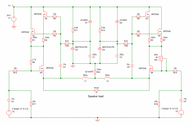
Alright, here's a revised version of the circuit that allows adjusting the Vgs for the LU1014. With this fix, I was able to set the DC bias to Vds = 2.4 V. This should work with just about any LU1014/LD1014 part out there, which removes the need for special/rare 1014 parts with unusually high Vgs specs. It's therefore much easier to build this amp.
I also found that with the earlier bias (Vds = 5...8V or so), the LU1014 gate was drawing a bit of current, whereas the gate current was essentially zero at Vds = 2.4 V. I prefer the setup with zero gate current.
I'd think it should be relatively easy to modify the LuFo PCB to add this (or a similar) Vgs adjustment for the LU1014, if desired.
Hi Mbrennwa,
What size potentiometer did you eventually use at the new position for controlling the gate bias on the LU1014D? I am guessing something like 20k? But best to see what you used that worked well and gave good adjustment range and sensitivity.
Hi Mbrennwa,
What size potentiometer did you eventually use at the new position for controlling the gate bias on the LU1014D?
I just used what came out of the parts box. I used a fixed 1 kOhm resistor from 28 V into a 50 Ohm trimmer pot to GND. For a proper build I'd user larger values.
- Home
- Amplifiers
- Pass Labs
- SuSyLu Where Are You?