Beautiful work as always! Have you considered porting the vents into the periphery of the horns? Actually, if you wanted, you can put a box around the horn and tune a port for your low-mids to reach lower and pipe the reflex into the horn. You can get circa 80Hz this way which is convenient when you want to play music without the big subs.
Sort of like this design that I was working with Weltersys and Jennygirl a while back.
http://www.diyaudio.com/forums/multi-way/262838-synergy-tripp-10-a-5.html


Sort of like this design that I was working with Weltersys and Jennygirl a while back.
http://www.diyaudio.com/forums/multi-way/262838-synergy-tripp-10-a-5.html

I missed the cardboard synergy - nice! I did the same with foam core of course and it worked beautifully. The tractrix synergy or Trynergy also sounds great - also made of foam core.
You and Legis are on this Ferrari red synergy horn trip - and it looks great! My next horns will be red. 🙂
Unity horn miniDSP settings
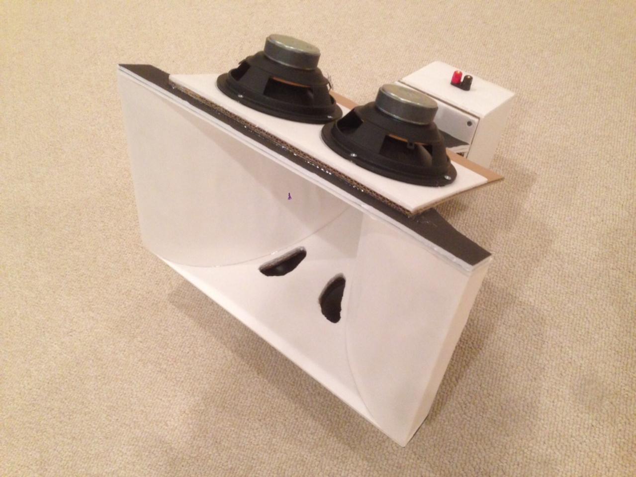
Some tinkering around with the Unity horns (attached a slightly better picture). After spending a few hours measuring and trying to get a grasp of what REW is interpreting on the impulse responses of the four channels, I arrived with the following:
Low 0ms
Low Mid 4.25ms
High Mid 8.46ms
High 8.96ms
It seems strange to me such a difference in delays but overall it seems to make a real difference in the way everything comes together. I went back to using LR4 crossovers on all channels as it cleans up the mids. The one thing I am struggling with is the mid to high crossover having a more pronounced dip at the crossover point with the impulse derived delay settings. If I move the delay around slightly there is more output around 1.2khz.
I don't understand entirely what's happening with the phase. If I calculate minimum phase in REW the resulting curves are fairly flat besides a lag in the lower mids but above 350hz stays close to perfect, the CD and mid woofers are really consistent too. The Dayton 8" reference woofer in a 1.8cu ft rear ported box acting as a sub seems to have a real lag to it but when given a forward (zero) delay it blends better with harder hitting bass.
I am really curious how the Dayton 6.5" woofers will do in the new horn when I get around to this "upgrade". I originally was going to build a 2 channel Unity type horn but realized with the dimensions I had just enough room to squeeze a 6.5" woofer in. Hornresp simulated nicely to around 90hz without too much cone displacement. I am hoping the cones won't slap the back horn wall as as they appeared to be inset far enough, otherwise I'll have to make some ring spacers to put under them, which will increase the back chamber volume.
I am hoping there is adequate low mid response out of the 6.5" woofers due to what seems to be slightly forward spacing of the ports (3/4"x4" oval centered around 9" from the throat) and approximating port size and back chamber volume with relation to what I entered into hornresp as this was difficult to determine. From what I understand the 1/4 wave of 350hz is around 9.6" so would this mean it should work without a null?
Attachments

synergy horn design
Wow, that's a cool design. The main reasoning behind the sealed back low mids is to avoid complicated porting which I have no idea how to simulate. It also appears there will be more consistent phase and less group delay than with porting.
Beautiful work as always! Have you considered porting the vents into the periphery of the horns? <snip>
Wow, that's a cool design. The main reasoning behind the sealed back low mids is to avoid complicated porting which I have no idea how to simulate. It also appears there will be more consistent phase and less group delay than with porting.
Low 0ms
Low Mid 4.25ms
High Mid 8.46ms
High 8.96ms
Something is off here - you are many multiple cycles off in the delay. The synergy should provide almost no extra delay required if you put the ports at their ideal locations. Even if you did not, the speed of sound means a 1ms delay is about 13.5 inches of propagation distance. Your horn depth appears to be no more than 2ft deep? So maybe 2ms of delay tops, but fact that woofer is out front, and mids slightly behind etc means delays should be under 1ms. You may have some additional delay due to the bandpass chamber, but not much.
The only way to measure the acoustic offsets properly is to measure it and use acoustic interference to get it exact. Read this article by Jeff Bagby:
http://techtalk.parts-express.com/attachment.php?attachmentid=36012&d=1367535655
Then set your mic up in a fixed position, say 1m from the horn mouth. Then take several measurements: tweeter only, mid only, bass only, tweeter and mid, tweeter and bass, but do it all without touching the mic or the speaker. All wiring switching. Then export the .frd files from REW into PCD and then tweak the offset z distance until the combined predicted interference sweep matches the measured one. This tells you the distance (or equivalent delay) to use.
Once you have measured the delays (and they will be close to initial estimates using a ruler based on 13.5in per millisecond (or 342 meters/sec), you can use these as estimates for the delays to put in miniDSP.
Alternatively, you can set up an LR2 XO on both tweeter and mid or tweeter and woofer, etc. Then you know that max null happens when relative delays are exact. So set frequency generator to XO freq and use RTA function in REW to monitor SPL level while adjusting in miniDSP the delay 0.02ms at a time to get the minimum null. Then flip polarity and you should see a max value. If you go to far, multiple cycles off it can still do this but you need to find the main one based on measured distance.
^I think you can use the last mentioned LR2 method only if the acoustic response of both bands is straight line far beyond the crossover point (say one octave). Not very likely scenario in a synergy. Acoustical filtering, if there is any from bandpass chamber, comp driver roll-off etc., turns the phase just like electrical filtering.
Last edited:
I agree with x something is off with your delays. How are you determining that from the impulse? Unless you're doing a dual channel measurement the delay shown for individual impulses will not be representative of the actual delay between drivers. REW can do dual channel measurements.
delay settings
Thanks for verifying this. I set REW to measure the impulse t=0 from sample start, and measuring one channel each individual output (L,LM,HM,H) using the minidsp to mute the channels. Obviously this method does not give an accurate time measurement. I'll read the article and try learning PCD.
Regards,
Nate
^I think you can use the last mentioned LR2 method only if the acoustic response of both bands is straight line far beyond the crossover point (say one octave). Not very likely scenario in a synergy. Acoustical filtering, if there is any from bandpass chamber, comp driver roll-off etc., turns the phase just like electrical filtering.
True, but I don't think Njones is putting XO's at the edge of his falloffs. If you have some overlap it will produce a cancellation null. I was able to see the null for instance between the mid woofers and full range drivers for my Trynergy easily enough with this method. The PCD method is exact but takes more time and work to do. OTOH, if you do the PCD method of importing all the FRD files you have the ability to tweak and check your xo and EQ in simulation before putting it into miniDSP. This can actually save time in the long run.
^I think you can use the last mentioned LR2 method only if the acoustic response of both bands is straight line far beyond the crossover point (say one octave). Not very likely scenario in a synergy. Acoustical filtering, if there is any from bandpass chamber, comp driver roll-off etc., turns the phase just like electrical filtering.
I am seeing a phase shift in the midrange output as it nears 300hz. In the new horn I may try moving up the xover point to 350 or 400hz - hopefully I can get the high/mid xover point higher than 1.2khz.
The 1.2kHz upper limit on the mids is set by the notch there that results from the reflection of the mid off the CD diaphragm and back to the mid. It can only be raised by making the distance between the mid port and CD closer. I believe we are all hitting a hard limit here as it can't get any closer.
Can you show a fullrange sweep of your mids? I would be interested to see how high it is and how deep the null is.
Can you show a fullrange sweep of your mids? I would be interested to see how high it is and how deep the null is.
Something is off here - you are many multiple cycles off in the delay. The synergy should provide almost no extra delay required if you put the ports at their ideal locations. Even if you did not, the speed of sound means a 1ms delay is about 13.5 inches of propagation distance. Your horn depth appears to be no more than 2ft deep? So maybe 2ms of delay tops, but fact that woofer is out front, and mids slightly behind etc means delays should be under 1ms. You may have some additional delay due to the bandpass chamber, but not much.
The only way to measure the acoustic offsets properly is to measure it and use acoustic interference to get it exact. Read this article by Jeff Bagby:
http://techtalk.parts-express.com/attachment.php?attachmentid=36012&d=1367535655
Then set your mic up in a fixed position, say 1m from the horn mouth. Then take several measurements: tweeter only, mid only, bass only, tweeter and mid, tweeter and bass, but do it all without touching the mic or the speaker. All wiring switching. Then export the .frd files from REW into PCD and then tweak the offset z distance until the combined predicted interference sweep matches the measured one. This tells you the distance (or equivalent delay) to use.
Once you have measured the delays (and they will be close to initial estimates using a ruler based on 13.5in per millisecond (or 342 meters/sec), you can use these as estimates for the delays to put in miniDSP.
Alternatively, you can set up an LR2 XO on both tweeter and mid or tweeter and woofer, etc. Then you know that max null happens when relative delays are exact. So set frequency generator to XO freq and use RTA function in REW to monitor SPL level while adjusting in miniDSP the delay 0.02ms at a time to get the minimum null. Then flip polarity and you should see a max value. If you go to far, multiple cycles off it can still do this but you need to find the main one based on measured distance.
The part I find perplexing is where the midrange distance should be measured from, also complicating things is the effect of the port. It would appear that the CD should be delayed slightly to match the mid? Otherwise using the physical offset distances seems simple enough to enter into miniDSP.
The part I find perplexing is where the midrange distance should be measured from, also complicating things is the effect of the port. It would appear that the CD should be delayed slightly to match the mid? Otherwise using the physical offset distances seems simple enough to enter into miniDSP.
It's always the distance from the mid cone to the port, then to the back to the CD diaphragm.
Last edited:
The 1.2kHz upper limit on the mids is set by the notch there that results from the reflection of the mid off the CD diaphragm and back to the mid. It can only be raised by making the distance between the mid port and CD closer. I believe we are all hitting a hard limit here as it can't get any closer.
Can you show a fullrange sweep of your mids? I would be interested to see how high it is and how deep the null is.
Here is the raw response with a high pass filter at 200hz:
Attachments


delay settings
I ended up with this based on the SPL measurements at xover points:
high 0.13ms
mid 0ms
low 1.65ms
sub 7.08ms
The woofers need more delay than their physical distance would indicate to avoid a null at 350hz.
The sub has a null at 70hz unless excessive delay is applied. Could this be from the back port and concrete wall reflections? Regardless I am not really concerned as these will be replaced with the new cabinets that have 15" sub drivers with front ports which will likely behave differently.
Here is the overall measured response at 1m, right channel after correcting the delays and adding minimal eq. The phase plot (which seems to be all over) vs minimum phase calculation - how is this interpreted?
Shorten the time window from 500ms to ~5-10ms (IR Windows button in REW), it will clean up the phase response. You can also scale the view so vertical lines are in 5dB or 10dB steps.
Last edited:
Here is the raw response with a high pass filter at 200hz:
You made it to 1.5kHz before the 10dB null - so that means the distance from your mid cone to the CD diaphragm is 4.49in (half wave distance based on 342m/sec speed of sound) or a 0.33ms delay.
Not bad actually, but means you need a fairly steep XO at about 1.2k tops.
From your measurements:
high 0.13ms
mid 0ms
low 1.65ms
sub 7.08ms
The 1.65ms says your woofers cone diphragms are 22.2in from the mid cone diaphragms. if you could have gotten your mids moved about 1.75in farther out, the delays for tweet and mid would have been zero. But since you have miniDSP no big deal.
These numbers look reasonable now. The sub has room reflections so doesn't matter.
Legis is right, use gate of less than distance to mic in time of flight. I sometimes place mic at 0.5m to avoid a floor bounce and set gate to 5ms.
Look at regular phase not minimum. If you do your crossovers right and transient perfect, you get what Bwaslo gets on his Cosyne (a very difficult thing to do unless clever low order filters are used).
Last edited:
Crossover rework
Thanks, this was very helpful. I went back to the Harsch XO settings and dialed in the delays properly (which I did not have correct the first time). Phase looks much better with a rise to 120 deg. around 1K but with no wrap. 🙂
miniDSP settings:
Sub: BW4 LP 70hz, 0ms
Low: BW4 BP 70hz/350hz, 0ms
Mid: Bessel BP 350hz/1200hz, 2.42ms
High: BW4 HP 1400hz, 3.12ms
I'll have to test further when everyone is not sleeping, which reminds me I probably should be.
- Status
- Not open for further replies.
- Home
- Loudspeakers
- Multi-Way
- Synergy Horn build thread - The Dreadnoughts