I have not been able to find any information, either online or in textbooks regarding the resistance looking into the collector of a Sziklai pair; I have assumed that it is, to a reasonable approximation, neglecting early effect, the product of the two transistors’ betas multiplied by the (degeneration) resistance in the emitter circuit, but can’t find any confirmation of this. The reason I am interested in this is that I wish to put a riaa network directly after a Sziklai pair. Many thanks.
The output impedance of the sziklai seems to be the lowest of all types of output stages as I always get the lowest distortion on 2 ohms loads with this topology in simulations and there's also an aidiophile amp which has a DF of 1000 with its variation of sziklai pair while 4 of the best powerful stage amplifiers of 2022 up to 2000watts/channel all have sziklai outputs including the No 1 Behringer EP 4000 which is a QSC clone, all the other 3 being also QSC amps.
Thanks dreamth, but I am using the Sziklai as a low distortion gain stage with the output at the collector, not in the usual emitter follower configuration.

Attachments

Do a simulation, probably back drive it from an AC current source. The choice of transistors does matter. And it will be frequency dependent so a sweep will be the thing to do. Or just simulate the entire circuit because you probably want to tweak it anyway. In most cases your Sziklai output will have an impedance 1000x lower than the RIAA network, so it doesn't matter much. LTC spice makes this 2EZ. Network calculations by hand is a recipe for frustration and mistakes.I have not been able to find any information, either online or in textbooks regarding the resistance looking into the collector of a Sziklai pair; I have assumed that it is, to a reasonable approximation, neglecting early effect, the product of the two transistors’ betas multiplied by the (degeneration) resistance in the emitter circuit, but can’t find any confirmation of this. The reason I am interested in this is that I wish to put a riaa network directly after a Sziklai pair. Many thanks.
Thank you Knutn, this is about what I would expect if I used ksa992 alone with a 100 ohm resistor in the emitter; clearly the betas do not multiply as they do with the input impedance.
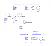
Ok, you can take the output from that side if the CFP. Not what I expected but perfectly reasonable.As you may see from the attached LTSpice-file, the output impedance is high (about 81 kohm) in this example.
But, the simulation drives 1 Amp into ~1K (the actual output impedance) resulting in 1000VAC, ie +60dBV.
If you replace the 1K RL resistor with a 9.5mA current source, you get about 83.9K. But you need a "RL" load to define the gain and to provide a pull down current. You never build a circuit depending on a collector/CFP/plate impedance because it's just not reliable and predictable. A real "constant current source" will give a high impedance, but it will not be infinite, probably something similar to the CFP.
You can build this circuit and it works just fine. Remember that the current source is for calculating the output source and is removed in real life (You may use 1 mA instead of 1 A, but the result is the same).
If I understand steveu's post correctly, he is aware that SPICE AC analysis linearizes the circuit around the bias point and that it therefore doesn't matter whether you use 1 uA, 1 A or 1 kA.
The point is simply that that 81 kohm or 83.9 kohm or whatever depends on transistor parameters that spread all over the place and that it is therefore not accurately known. Shunting it with an accurate 1 kohm resistor solves that, but of course much reduces the impedance.
The point is simply that that 81 kohm or 83.9 kohm or whatever depends on transistor parameters that spread all over the place and that it is therefore not accurately known. Shunting it with an accurate 1 kohm resistor solves that, but of course much reduces the impedance.
I have tried to make a small signal calculation omitting R6 in the figure and using the beta and ro numbers from the simulation. The result is about 80 kohms. But from the equations it is obvious that the final result is very parameter dependent, especially the beta and ro numbers.
Knut, it is precisely the equations for small signal collector impedance for the Sziklai that I have been unable to find in any textbook; at a quick glance, Q8 looks like an emitter follower but it can’t be since its collector is connected to Q5’s emitter. Although Sziklai seems like an excellent, linear gain stage, it seems as if it is rarely used as such.
Like a pentode, "very high!". Why does it matter? In a real circuit the collector is shunted by either a much lower resistor or another transistor. If you transistor-load and optimize everything, the voltage gain is HUGE, too huge to use directly, only inside NFB. And very-very dependent on junction processing details that the maker controls very lightly.
True, but how do you know how low the much lower resistor has to be when you don't know how high very high is?
If it is much lower, it does not matter much.how low the much lower resistor has to be
The example in reply #6 is flowing 9mA at 20V.
It could certainly drive a 1k EQ resistor even at high level.
The Rout estimate is 70k, so pencil 50k-100k.
The "1k" EQ resistor may be in effect 990r or 980r, 1% or <0.1dB differences.
Even if the Sziklai turns out to truly be 1Meg, the EQ resistor is in effect 999r, <1% error.
If you must have more precision than 1% (analog orbital computer), and have <1% resistors and capcitors, you may need a different technique. Though I assure you that no record cutter can hold 0.1dB over a whole side.
Of course, but if you had estimated "very high" to be > 1 Mohm and had chosen a 10 kohm resistor (with a current source in parallel to make it fit in the supply voltage), the circuit would be quite inaccurate. That is, it's nice to have an order of magnitude estimate.
Anyway, it's about 80 kohm, so an accurate 1 kohm in parallel will do well.
Anyway, it's about 80 kohm, so an accurate 1 kohm in parallel will do well.
Both are ~~100:1 order-of-magnitude differences? Is that what you wanted to type?if you had estimated "very high" to be > 1 Mohm and had chosen a 10 kohm resistor (with a current source in parallel to make it fit in the supply voltage), the circuit would be quite inaccurate. That is, it's nice to have an order of magnitude estimate.
Anyway, it's about 80 kohm, so an accurate 1 kohm in parallel will do well.
1M:10k == 100:1 (actually more accurate)
80k:1k == 80:1
What I mean is, if not having a clue about the actual impedance, you would have estimated it to be > 1 Mohm while it is only about 80 kohm, then you might end up with an inaccurate circuit.
Yes, my original circuit, before modified to Sziklai used a 2sc4495 with beta about 2000 and 1k emitter degeneration. Therefore I could be certain that using 7k5 as the upper RIAA resistance as collector load would be unaffected by the impedance looking into the 2sc4495 collector. My concern is whether adding a Sziklai transistor (bc558) would have impacted the RIAA response.
As a designer you are interested in knowing what you may expect of the size of bias values, input impedance, output impedance, gain, frequency range etc, etc. I don't want to design anything with wild guesses as a leading design method. If you in this case are using the configuration in post #6 in a symmetric way as a VAS (see the figure), it is in fact important to know which value the output resistance may have.
If I have the time this weekend, I'll try to show what I ended up with my "calculations" using quite simple pi-models.
If I have the time this weekend, I'll try to show what I ended up with my "calculations" using quite simple pi-models.
Attachments

- Home
- Source & Line
- Analogue Source
- Sziklai pair collector resistance