Graham,
These boxes are back loaded, maybe it's not the right for this circuit as you say. Though T-bass do make a difference, as "jump factor" is better with the circuit.
What I wonder about my transformers is still the inductance of coils. CLS mentioned his coils were around the 300's mH, while mine are much lower. At least according to my meter.
Cheers
http://www.diyaudio.com/forums/atta...5833d1207687672-sonido-bib-march-2008-003.jpg
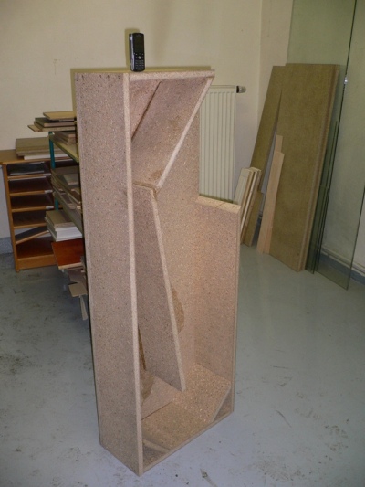
Wonder if the Sonidos would reproduce better with their backs removed ?
These boxes are back loaded, maybe it's not the right for this circuit as you say. Though T-bass do make a difference, as "jump factor" is better with the circuit.
What I wonder about my transformers is still the inductance of coils. CLS mentioned his coils were around the 300's mH, while mine are much lower. At least according to my meter.
Cheers
http://www.diyaudio.com/forums/atta...5833d1207687672-sonido-bib-march-2008-003.jpg
Please don't say that. Graham has been extremely patient and helpful in replying my (stupid) questions. I guess he's just tired (to fight against the questions with negative attitude, which there had been a lot already... )
And here's another reference of waveforms research: Active Filters
Scroll down to about 1/3 of the page to the bottom - Linkwitz Transform.
And here's another reference of waveforms research: Active Filters
Scroll down to about 1/3 of the page to the bottom - Linkwitz Transform.
StigEric.
Thank you CLS.
As you point out - the information has already been published.
Also StigEric,
see 2/3 down the page CLS references;
see the illustrated first cycle inadequacy which T-bass counters in a manner EQ etc cannot.
Hi Peter.
Do try taking the back off one of your Sonidos - might prove worthwhile ?
If your transformer impedance above about 150mH - very likely OK with decent amplifier.
.
Last edited:
Hm... this circuit looks simple, but what it seems to do is rather complicated. Takes a while to get the hang of it. ")
Now - if we wanted to create a T-bass circuit that did not EQ the response at, and below, driver Fs, what would that look like? No EQ... just compensate for the initial wave distortion. Would that even be possible?
I understand that the parts between the transformer and driver can be omitted, as they mainly do EQ at higher frequencies.
EDIT: I have to look for a big toroid now. Damn.
Last edited:
Graham,
I suppose you mean inductance. The problem is that I measure ~20mH with a multimeter, which of course can be wrong. Oh well, I have to find someone to measure more accurately....
Regarding taking off the back of Sonido boxes. No, I won't do that, I have other plans for T-bass...
Thanks a lot for replying!
Cheers
If your transformer impedance above about 150mH
I suppose you mean inductance. The problem is that I measure ~20mH with a multimeter, which of course can be wrong. Oh well, I have to find someone to measure more accurately....
Regarding taking off the back of Sonido boxes. No, I won't do that, I have other plans for T-bass...
Thanks a lot for replying!
Cheers
Ok, so I did test quite a few drivers tonight, and they all showed the same thing: as claimed, the first cycle of a sine wave indeed comes out distorted, as my recordings below illustrate quite clearly. Graham was right, I didnt understand, and I am sorry that my doubts led to negativity in the thread.
By why on earth is this problem not more widely known?
The graphs were made this way:
1. 100 ms long 70 Hz sinewave generated in Samplitude. This was played back while recording with Samplitude.
2. Playback was send directly to the speaker (no filters)
3. The acoustic output was recorded with Samplitude using a high-quality omni condenser microphone.
4. The curves are the recorded sinewave as shown in Samplitude from two very different drivers, one 21" and one 5".
By why on earth is this problem not more widely known?
An externally hosted image should be here but it was not working when we last tested it.
An externally hosted image should be here but it was not working when we last tested it.
The graphs were made this way:
1. 100 ms long 70 Hz sinewave generated in Samplitude. This was played back while recording with Samplitude.
2. Playback was send directly to the speaker (no filters)
3. The acoustic output was recorded with Samplitude using a high-quality omni condenser microphone.
4. The curves are the recorded sinewave as shown in Samplitude from two very different drivers, one 21" and one 5".

OK, I build this circuit, based on CLS' suggestion on page 4 in this thread.
It actually made the waveform worse.... what's up with that?? Is the transformer too small?
Waveform (70 Hz):
An externally hosted image should be here but it was not working when we last tested it.
It actually made the waveform worse.... what's up with that?? Is the transformer too small?
Waveform (70 Hz):
An externally hosted image should be here but it was not working when we last tested it.
Hi StigEric,
You asked
>> But why on earth is this problem not more widely known? <<
Answer because everyone looks at and measures continuous sines for LS amplitude responses, distortion etc.
'Music' is NOT continuous sines in sine time, but is continuously changing waveforms in music time.
Regarding those loudspeaker traces you have developed; imagine the harmonics of those waves as would already be developed within that first cycle; they will be coming through say the mid range.
Imagine how distorted the resultant propagating bass/ mid composite would be during that first cycle especially.
When there is dynamic compensation for the first cycle error (which EQ cannot do) a drum or bowed bass etc. starts to sound much more like the real thing because that first mistimed half cycle zero crossover no longer creates composite error between the fundamental note and its own harmonics.
This very same first cycle error effect applies to series capacitors in amplifiers,
AND
to NFB arrangements,
though leading edge NFB errors arise in mid/ treble ranges, this being why high NFB SS amplifiers can sound inferior whilst measuring superbly via time isolated sine testing.
...
By why on earth is this problem not more widely known?
An externally hosted image should be here but it was not working when we last tested it.
An externally hosted image should be here but it was not working when we last tested it.


Michael
Here's an other one with a lower value resistor in series with the 1100 uF cap. The waveform is surely modified, but nothing happens to the first cycle. As you can see, the second and third cycle is boosted.
An externally hosted image should be here but it was not working when we last tested it.
Last edited:
Re Post #311:
Transformer input and centre tap transposed ?
I dont think so....
My transformer dont have a center tap, there are two individual windings that I've conneted in series. The connection point is used as center tap, and the amp is connected there.
Here's an other one with a lower value resistor i series with the 1100 uF cap. ...
???
The 1 ohm resistor in series with the cap is 0.5 ohms instead.
The 1 ohm resistor in series with the cap is 0.5 ohms instead.


Michael
- Home
- Loudspeakers
- Full Range
- 'T'-bass drive for OB LF drivers.