Broke Down and bought the Seas L15RLY/P-04 5" Thought there would be plenty of Designs that would tackle the Cone break but not so As you can see this is a Production run of the never offered (to the Public ) 4 OHM version of the speaker there is a break up around 8K that looks nasty, very similar to the 8 OHM version THE question is Can the FIX applied to the 8OHM version be applied to this driver with Minimal Tweaks ( Value Adjustments )
I don't want to go active Crossover looking for a little Guidance as I don't have a clue If you are wondering I also Picked up the
27TDFNC/GW (H1462) 1" to pair with it (upon Recommendation ) Buy the way still on sale at Madisound anyway any help would be appreciated Thanks in advance Steve
I don't want to go active Crossover looking for a little Guidance as I don't have a clue If you are wondering I also Picked up the
27TDFNC/GW (H1462) 1" to pair with it (upon Recommendation ) Buy the way still on sale at Madisound anyway any help would be appreciated Thanks in advance Steve
Attachments

Last edited by a moderator:
Hmm, the 08 has a 2.6 cm dia. VC, so assume the 04 does too, which appears to be true based on its published response = VC Hz = ~34400/pi/2.6 = 4211.5 with above this point is normally the dustcap or phase plug in this case, so if it has the same phase plug, then the electronic solution should in theory fix it.
One way to tackle the break up is to add a “tank” in parallel to the first inductor in your woofer low pass filter. This is a capacitor (usually pretty small) and resistor (typically around 15-20ohms) in series placed in parallel with the inductor. This creates a deep notch, changing the capacitor value changes the notch frequency and the resistor the depth of the dip.
Troels Gravesen used it in his SBA761 for a 3.5khz tank, below I.e. 68 ohms and 0.1uF, this was a public design and is available on the way back machine.
You can also add a traditional parallel notch LCR filter.

Troels Gravesen used it in his SBA761 for a 3.5khz tank, below I.e. 68 ohms and 0.1uF, this was a public design and is available on the way back machine.
You can also add a traditional parallel notch LCR filter.
Attachments


WHY would you worry about that nasty 8kHz peak when you should NEVER EVER reach it?

Frequency response drops dramatically above 2kHz, in fact it starts rolling down above some 1400Hz, matching its
It is NOT repeat NOT a full range unit which can be augmented with a tweeter ... not a very small tweeter as you think.
Mechanical resonances are ugly and hard to tame, best is to avoid them altogether, with the proper crossover.
DSP won´t help you here.
You are most probably right, the complicated/expensive part of speaker manufacturing is the magnet/polepiece/frame assembly requiing expensive dies and semi expensive punching and turning, so usually manufacturers make one type and then try to assemble as many models as plossible on it.
It´s logic to keep VC/polepiece diameter if at all possible.
Frequency response drops dramatically above 2kHz, in fact it starts rolling down above some 1400Hz, matching its
description.long throw high fidelity woofer or woofer/midrange unit
It is NOT repeat NOT a full range unit which can be augmented with a tweeter ... not a very small tweeter as you think.
Mechanical resonances are ugly and hard to tame, best is to avoid them altogether, with the proper crossover.
DSP won´t help you here.
Hmm, the 08 has a 2.6 cm dia. VC, so assume the 04 does too
You are most probably right, the complicated/expensive part of speaker manufacturing is the magnet/polepiece/frame assembly requiing expensive dies and semi expensive punching and turning, so usually manufacturers make one type and then try to assemble as many models as plossible on it.
It´s logic to keep VC/polepiece diameter if at all possible.
A coat pf ModPodge/Puzzlekoat will help.
But keep the XO low enuff and the issues should be out of band.
dave
But keep the XO low enuff and the issues should be out of band.
dave
That is a valid question and one I poised to myself, I read somewhere that despite a deep crossover curve the breakup was audible is that erroneous ? believe me I dont want to do more that necessary The recommended crossover point for the tweeter is at 2400 or so i thinkWHY would you worry about that nasty 8kHz peak when you should NEVER EVER reach it?
Frequency response drops dramatically above 2kHz, in fact it starts rolling down above some 1400Hz, matching its
description.
It is NOT repeat NOT a full range unit which can be augmented with a tweeter ... not a very small tweeter as you think.
Mechanical resonances are ugly and hard to tame, best is to avoid them altogether, with the proper crossover.
DSP won´t help you here.
You are most probably right, the complicated/expensive part of speaker manufacturing is the magnet/polepiece/frame assembly requiing expensive dies and semi expensive punching and turning, so usually manufacturers make one type and then try to assemble as many models as plossible on it.
It´s logic to keep VC/polepiece diameter if at all possible.
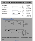
would either of these crossovers be OK ? on better ? off generic crossover design software
Attachments
-
 Screenshot 2022-12-24 at 11-22-40 Speaker Crossover Calculators by V-Cap.png8 KB · Views: 104
 -
 Screenshot 2022-12-24 at 11-22-58 Speaker Crossover Calculators by V-Cap.png8.6 KB · Views: 96
 -
 Screenshot 2022-12-24 at 11-22-58 Speaker Crossover Calculators by V-Cap.png8.6 KB · Views: 99
 -
 Screenshot 2022-12-24 at 11-12-16 SEAS Prestige 27TDFNC_GW (H1462) 1 Textile Dome Tweeter.png88.5 KB · Views: 103
Generic crossover calculators rarely give good results, you need to build your enclosure based on the bass response you want form the woofer, then measure the frequency and impedance responses and use these in a proper simulation software to design the crossover. A basic observation is that you have used 8 and 4 ohms for the speakers but if you look at the impedance curves, at 2400hz the woofer is more like 7 ohms and the tweeter 6 ohms.
A proper simulation calculator ? I know there are some that use the traced curve, to develop a solution. are these Adequate ? I do not have evaluation equipmentGeneric crossover calculators rarely give good results, you need to build your enclosure based on the bass response you want form the woofer, then measure the frequency and impedance responses and use these in a proper simulation software to design the crossover. A basic observation is that you have used 8 and 4 ohms for the speakers but if you look at the impedance curves, at 2400hz the woofer is more like 7 ohms and the tweeter 6 ohms.
further Are the particulars noted in the spec sheet WxHxD ( 180mm x 210mm x 290mm )a good place to start as they were the basis of the generated Curve presented ? it seems so ? what is the downside ? Finally I think I imputed the values correctly I will double check
Are you saying that I am safe Lets say 2 octaves Below the peak ? I guess that is a lot of real estate that will work .any slope recommend ?(For a complete answer I would rather see polar measurements.)
However simply you can stick to crossing the response down far enough before breakup. Breakup starts lower than the peak. If notch filtering is required for a smooth rollof, then it is required.
Ok, here's a simulation. When measured in a real baffle it might be different, but let's go for it. This plot shows the response before the crossover, and with the crossover.. and the magenta plot is a nice fourth order Linkwitz-Riley low pass at 2,500Hz target curve.
Now you can see the 8kHz peak is down around 20dB. Is that enough?
Simple answer, yes. Feel free to take it down a few more dB with a notch if you prefer.
Complicated answer, If I was listening off-axis and the 0 degree axis was not straight on to a reflection then I'd average the angles. It's a possibility that this could be left as it is.
Very Kind of you ! And yes that looks as it would work, Interesting That this approach Flattens the bump in the response, I think I will try it as I have the parts. Will it matter that the tweeter is rated at around 90db ? I suppose the extra sensitivity available can be used to shape the sound, most easy would be in the upward vein,obviously some attenuation needs to be implmented , this begs the question what would the upward slope LIMIT be that would be listenable ?(Pleasing )
Adam at madisound seems to think the seas would integrate well .I hope that is so. on the other hand I see that some prefer a downward bias, would you say that the average implementation lends itself to a rather strident presentation ? My observation is is that one needs to be careful about the source material and the recording. EVA Cassidy's an Rikki lee Jones works are among the pieces I think are worthwhile to get a better picture of what might be what is going on Again thank you for the simulation Steve
Adam at madisound seems to think the seas would integrate well .I hope that is so. on the other hand I see that some prefer a downward bias, would you say that the average implementation lends itself to a rather strident presentation ? My observation is is that one needs to be careful about the source material and the recording. EVA Cassidy's an Rikki lee Jones works are among the pieces I think are worthwhile to get a better picture of what might be what is going on Again thank you for the simulation Steve
Last edited by a moderator:
Yes, a downward trend is popular. We're only talking 1-2dB per octave on average. I'm not sure it is as simple as that straight line, but I've found it makes the task of smoothness easier to achieve... ie even on speakers that could be successfully voiced with less tilt.
Some of your more significant concerns will be setting the tweeter level, matching the tweeter crossover slope, setting the overall level according to what will leave you sufficient bass response.. and the baffle step.
Some of your more significant concerns will be setting the tweeter level, matching the tweeter crossover slope, setting the overall level according to what will leave you sufficient bass response.. and the baffle step.
Yes, the slopes are somewhat of a match in the opposing directions.Interesting That this approach Flattens the bump in the response,
More complex answer; Studies have shown that breakup should be -25dB at minimum, that -40dB is preferred or better, and -50dB is deemed inaudible.
Well, I think this depends on how the breakup is handled. If the breakup is attenuated by just the crossover slope (without additional notch filtering), it still "sticks out" from the slope (see post #12) and probably more audible than a properly notch filtered breakup when the breakup peak (actually no longer a frequency response peak because of the notch filter) is slips into the acoustical slope of the crossover.
Moreover, experiments showed that using the mentioned "tank circuit" to filtering the breakup can reduce the breakup related harmonic distortion too but the "parallel to the driver" notch filter are not (or not as much).
Moreover, experiments showed that using the mentioned "tank circuit" to filtering the breakup can reduce the breakup related harmonic distortion too but the "parallel to the driver" notch filter are not (or not as much).
Last edited:
Thanks @YSDR for the suggestion.
The viability of the two filter types will depend on the impedances presented by the circuit. Often it is suitable for breakup work for this reason.
In this case I was able to get very similar results with both versions. (caution: the overall impedance in the second option falls below 4 ohms above 100kHz, so watch it if tweaking.)
Either of these options seem like a good match for the PROBLEM , I am trying to wrap my head around why one be preferred over the other I see you referencing the impedance of the Circuit. I am thinking that the design options ( tweeter crossover interaction ) As a Whole that is Summed ? ( I don't know if this is correct ) will present a impedance picture that will determine the best course of action, That is Identify the best Option?
Again apologies for my lack of understanding ,Doing my best but this is harder than it looks like Initially at least for me
Again apologies for my lack of understanding ,Doing my best but this is harder than it looks like Initially at least for me
As a quick note (please forgive the phrasing -being Christmas day, brevity is calling 😉 ):
The main bell mode amplifies the baseline harmonic distortion at sub-multiples of its frequency. So with the main mode at 8KHz, if you look at harmonic distortion sweeps, HD2 will show a spike at 4KHz, HD3 @ 2.667KHz, HD4 @ 2KHz, HD5 @ 1.6KHz. There is also a smaller mode at 6KHz, which may start to show up in the distortion plots also, albeit to a lesser extent. Since this is a metal cone Seas unit, the motor design is almost guaranteed to be reasonable, although not state-of-the-art (since Seas generally prefer to get the basics as right as possible rather than simply hurling Faraday shielding at everything, which can see costs spiral). So you can probably cross it up to about 2.5KHz, LR4, or maybe even quasi-LR3, and providing the stopband mode is shunted down far enough not to affect the system response, you're unlikely to have any audible issues with resonance amplification.
If you want to cross a bit higher, then you're likely going to need a parallel bottomless notch (parallel inductor & capacitor placed in series with the driver -no resistor) tuned to that main breakup mode to create a high impedance 'blocker' for the current in the motor. A series notch (inductor & capacitor in series, placed in parallel with the driver) doesn't do that. It can have its uses in helping shape the frequency response to a given target curve, but it doesn't affect the distortion amplification at lower frequencies. As noted though, providing you cross LR4 < about 2.5KHz, you should hopefully be okay without needing to worry about that.
I'd avoid this type of driver at any cost, unless it's other qualities far outweigh the massive peak. IME, drivers like this never sound clean enough at higher drive levels, even with filtering it electrically. The tendancy for mechanical resonance will always be there and can be excited by higher order harmonics from the driver itself and even other sound sources ie the tweeters acoustical emissions in the woofer's peak band itself - yes I'm dead serious. I'll probably get bombed with criticism for saying this, but for my ears its how I perceive it.
If you do use that driver, the sharp 15dB peak along with the secondary one up higher will have to be attenuated more than 24dB to be considered out of band audibly. The off axis response could still make it an issue though and other peaks may still appear. 30dB down would be the minimum for my ears. Some people may not mind it being less than 24dB down, but it would bother me for sure based on previous builds I've done with metal cone drivers. I even notch some paper cone woofers with only 5dB breakup peaks in the mids. It makes a massive difference in the overall SQ.
IMO, a parallel notch is better than a series tank in terms of "forcing" the peak to be attenuated vs just subtracting it resistively - that can interact with amplification and other things in series with the driver. From an economic standpoint it could make sense to use a series tank, but for me it wouldn't be the best way to remove it IMO. Plus, having the peak that high up calls for much smaller and cheaper parts anyways, so why not do it the preferred way?
- Home
- Loudspeakers
- Multi-Way
- Taming SEAS metal woofer Break up ?