Hi all,
I've recently acuired some Tannoy Mercury Mk2 speakers - which (imo) look great, but are in need of some work.
The crossover seems quite basic and I've had a go at drawing it out - but surprised at the lack of capacitor in the woofer circuit?
Does this seem odd or is this how 80's speakers were designed?
I've measure the resistors (3.3 & 10) , the capacitor has measurements marked on it (6.8ohm 100v) and asked someone to measure the inductors for me (as I don't have the skills/tools!).
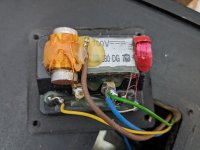
Here are some of the specs and images of the crossover below:
Peak power - 120 watts
Impedance - 8 ohms
Sensitivity Domestic - 93dB
Sensitivity Anechoic - 90dB
Frequency response +- 3dB nominal - 52Hz - 23Hz
Phase response - Better than +-45 between 120Hz-10kHz
Crossover frequency - 3kHz
Crossover type - First order low pass, second order high pass hard wired low loss
Colours in the diagram correspond to the photos (lower resistor is 10ohn, upper is 3.3)

resistors are hidden under some glue so marked them:


I've recently acuired some Tannoy Mercury Mk2 speakers - which (imo) look great, but are in need of some work.
The crossover seems quite basic and I've had a go at drawing it out - but surprised at the lack of capacitor in the woofer circuit?
Does this seem odd or is this how 80's speakers were designed?
I've measure the resistors (3.3 & 10) , the capacitor has measurements marked on it (6.8ohm 100v) and asked someone to measure the inductors for me (as I don't have the skills/tools!).
Here are some of the specs and images of the crossover below:
Peak power - 120 watts
Impedance - 8 ohms
Sensitivity Domestic - 93dB
Sensitivity Anechoic - 90dB
Frequency response +- 3dB nominal - 52Hz - 23Hz
Phase response - Better than +-45 between 120Hz-10kHz
Crossover frequency - 3kHz
Crossover type - First order low pass, second order high pass hard wired low loss
Colours in the diagram correspond to the photos (lower resistor is 10ohn, upper is 3.3)
resistors are hidden under some glue so marked them:
Attachments
In terms of more work, what is it that they need ?
Some of the soldering looks quite ropey that could do with a clean up and re flowing. I would check the other crossover to verify that it is the same build standard in case anyone has been tinkering before.
No capacitor on the woofer would indicate that the designer could obtain the frequency response he wanted with just a simple first order on the bass driver.
The crossover is nice and simple and their are not many components, so short of them being broken or burnt i don't expect replacing the components will provide a major change in their sound.
The crossover seems quite basic and I've had a go at drawing it out - but surprised at the lack of capacitor in the woofer circuit?
Your crossover schematic is a work in progress!
")
There is a first order (inductor only) low pass filter on the mid/bass driver and a second order (capacitor + inductor) high pass filter on the tweeter - a common arrangement.
I would caution against changing components in the crossover, particularly inductors. They will have been chosen carefully by Tannoy to provide the desired acoustic balance.
Consider that changing components without access to measurement equipment can make the speaker sound worse rather than better.
I would check the other crossover to verify that it is the same build standard in case anyone has been tinkering before.
That physical crossover does look rather scrappy!
The red insulating tape around the air core inductor makes me think the crossover may well have been tinkered with.
We are happy to engage with you!
To help you draw your crossover schematic accurately, here is the basic first order (woofer) second order (tweeter) filter combination:

In addition, the tweeter in your crossover is attenuated using an L pad arrangement of two resistors placed directly in front of it as shown below:

To help you draw your crossover schematic accurately, here is the basic first order (woofer) second order (tweeter) filter combination:
In addition, the tweeter in your crossover is attenuated using an L pad arrangement of two resistors placed directly in front of it as shown below:
Last edited:
Drawing the thing more conventionally it looks like this if I guess crossover coil values:

It's a reflex 8" polycone with a SEAS 25mm fabric dome by the looks:

Quite a standard crossover in commercial speakers. The 6.8uF is on the large side for a 3kHz crossover, and impedance must dip low at high frequencies.
https://www.hifiengine.com/manual_library/tannoy/mercury.shtml
I would have thought 4.7uF would work here. Oh, I see I should have put a 3.3R in the tweeter circuit.
Best, Steve.
It's a reflex 8" polycone with a SEAS 25mm fabric dome by the looks:
Quite a standard crossover in commercial speakers. The 6.8uF is on the large side for a 3kHz crossover, and impedance must dip low at high frequencies.
https://www.hifiengine.com/manual_library/tannoy/mercury.shtml
I would have thought 4.7uF would work here. Oh, I see I should have put a 3.3R in the tweeter circuit.
Best, Steve.
@system7 You have referred to the original Tannoy Mercury not the Mercury Mk 2 that I've pictured below.

Thanks for the crossover schematic. I was rather hoping that the OP would use my information to modify his attempt and learn something in the process.
Thanks for the crossover schematic. I was rather hoping that the OP would use my information to modify his attempt and learn something in the process.
Yes, the above are the Mk2's with the gold detail - very 80's!
Apprecate all the replies - thanks!
I was planning on at least replacing the capacitor which, at 35+ years old (assuming no-one has updated) is more than likely degraded. While I was at it. I would replace the resistors (as they are sealed in) and tidy up the wiring.
These are speakers I don't mind playing with to learn something (I've build a DIY kit before but not altered existing) and will pass over to my son if I can get them sounding acceptable. And yes, I don't have measuring equipment so would have to be listening and playing around. I can leave the existing speaker as is to compare.
The cabinets themselves need a little work so while I wait for the inductors to be measured (I can trial with original and new), I can work on those also.
The capacitor is a film type and these do not degrade with time. Only electrolytic capacitors do that.
Tannoy fitted a film type as standard, making their crossover "time proof".
But by all means replace it as an exercise in renovating loudspeakers. Use a polypropylene capacitor like this one:
https://wilmslowaudio.co.uk/monacor-mkp-polypropylene-capacitors/68-fd-monacor-mkp-capacitor
And these resistors are just fine for the job: https://wilmslowaudio.co.uk/resistors
As for inductors, I don't see any point in replacing them. Substitutes would need to have identical inductance and DC resistance values in order not to upset the crossover function.
I just had a delve in my dusty component boxes....

Those black and pink components on the right are Wilmslow/Monacor Supasound 250V Capacitors. 3.9uF to 8uF.
The Yellow ones are old Maplin 10uF and 3.3uF 630V MKP films. Quite huge! The three white things are standard 10W/7W/3W ceramic resistors.
In the middle are three coils. A black 0.5mH Maplin aircoil, an enamelled 0.3mH I pulled out of an old speaker and a 1.5mH ferrite for bass circuits.
The black and gold things are Mundorf electrolytics. Curiously the 70V 16uF is bigger than the 100V 22uF. They are cheap!
I show some solder and some tinned copper 20A fuse wire which is good for hooking stuff up. Also an old Wharfedale Linton crossover that I put a new 4.7uF MKP into.
Above the red coil is a Zobel network, 0.22uF and 15R. I put these on tweeters if it my whim.
Here's an old speaker cable I made for an old speaker with screws on the input.:

Hot glue is quite easy to melt off in a bowl of boiling water. This is OK because most components are rated near 100C, though the capacitors might take a beating.
You should be thinking of getting a good 40W+ soldering iron at screwfix, because modern leadfree solder needs high temperature, and a few tools like long-nose pliers too.
I have an inductance multimeter and a crimp set, for instance.
Those black and pink components on the right are Wilmslow/Monacor Supasound 250V Capacitors. 3.9uF to 8uF.
The Yellow ones are old Maplin 10uF and 3.3uF 630V MKP films. Quite huge! The three white things are standard 10W/7W/3W ceramic resistors.
In the middle are three coils. A black 0.5mH Maplin aircoil, an enamelled 0.3mH I pulled out of an old speaker and a 1.5mH ferrite for bass circuits.
The black and gold things are Mundorf electrolytics. Curiously the 70V 16uF is bigger than the 100V 22uF. They are cheap!
I show some solder and some tinned copper 20A fuse wire which is good for hooking stuff up. Also an old Wharfedale Linton crossover that I put a new 4.7uF MKP into.
Above the red coil is a Zobel network, 0.22uF and 15R. I put these on tweeters if it my whim.
Here's an old speaker cable I made for an old speaker with screws on the input.:
Hot glue is quite easy to melt off in a bowl of boiling water. This is OK because most components are rated near 100C, though the capacitors might take a beating.
You should be thinking of getting a good 40W+ soldering iron at screwfix, because modern leadfree solder needs high temperature, and a few tools like long-nose pliers too.
I have an inductance multimeter and a crimp set, for instance.
Yes, the above are the Mk2's with the gold detail - very 80's!
For the record, the Mercury Mk 2's tweeter is a Tannoy design.
It has a 25 mm polyamide (soft plastic) dome which is mounted on a specially cast asymmetric front plate.
impedance must dip low at high frequencies.
On test, the impedance of the Mercury Mk 2 averaged 8 ohm, but there was a dip in impedance to 3.8 ohm over a short stretch around 6 kHz.
The speaker achieved a "Best Buy" rating in the 1986/87 Hi-Fi Choice guide to buying Hi-Fi. Typical price per pair, incl VAT, was £150.
I hadn't noticed @Galu's remark about the tweeters being polyamide when I did this, but we can deal with any rising top end from a plastic tweeter separately, if necessary. Often the grille cloth tames them.
Because I am interested in this type of speaker, I looked into the use of an LCR on the bass, and a third order tweeter filter in negative polarity. I compared it with the original which is the dotted lines:

Thus:

The Phase is a nice 90 degree Butterworth:

The Electrical response is then this:

Not much different on the tweeter, just a tidge steeper and higher impedance, but the bass gets a lot more rolloff in the break-up region. Which will sound way cleaner.
I reused as many components as I could. Don't fret about it being done with Visaton drivers. These are predictable changes for most drivers.
I will try this myself. I usually use just a similar capacitor and resistor on the bass. I have the parts.
Because I am interested in this type of speaker, I looked into the use of an LCR on the bass, and a third order tweeter filter in negative polarity. I compared it with the original which is the dotted lines:
Thus:
The Phase is a nice 90 degree Butterworth:
The Electrical response is then this:
Not much different on the tweeter, just a tidge steeper and higher impedance, but the bass gets a lot more rolloff in the break-up region. Which will sound way cleaner.
I reused as many components as I could. Don't fret about it being done with Visaton drivers. These are predictable changes for most drivers.
I will try this myself. I usually use just a similar capacitor and resistor on the bass. I have the parts.
we can deal with any rising top end from a plastic tweeter separately, if necessary.
Remember that the tweeter has a "soft" plastic dome. It's similar to the one on my B&W DM110 whose shape I can temporarily deform with very light finger pressure.
The Hi-Fi Choice test results indicated that frequency response limits of +/-3 dB were easily met from 55 Hz to 20 kHz. A mild prominence was evident at 1 kHz, but otherwise the curve was most presentable.
Often the grille cloth tames them.
That's another thing on the list to make for these - none were with the speakers!
Thanks for the work there - I wasn't expecting such a detailed response!
Would you recommend the crossover is built as per this schematic?
I'm curious as to why the electrical response on the woofer plateaus between 5000 Hz and 20000 Hz. The filter response gets to almost -20dB by 5000Hz or so, but then stops attenuating any further. Would not a continuing roll-off be preferred?The Electrical response is then this:
View attachment 1325350
Not much different on the tweeter, just a tidge steeper and higher impedance, but the bass gets a lot more rolloff in the break-up region.
Old Visaton Boxsim 1.2 for Windows is, uniquely, still available here, thanks to yours truly:
https://www.diyaudio.com/community/...-from-visaton-free.267787/page-2#post-7126272
I like it, especially on phase, which always interests me. And you can import all the Visaton designs quickly.
It's quite an education in all the various trickeries you can employ with filters. I often put approximated designs into it to see what they do.
@witwald. I often use 8.2R and 4.7uF shunt with 1.5mH coils on 8" drivers for more rolloff . It's a bit better than just a bass coil. I have had good results with tank notches too, which are, say, 22r and 0.68uF across the bass coil for 5kHz notch.
An LCR notch is a more tidy way to do much the same thing.
@braddo88. I'm probably in a better position to dabble with an approx 5kHz LCR here in my 8" speakers. The red 3.3R, say 3 or 7W, is select on test for tweeter level. But I have a lot on at the moment. The modelling looks good, but you never know till you plug it in.
For sure low breakup is a very good thing in a speaker. It's the hobby. But quite a serious investment in basic equipment.
I am still using this approximate setup, though that is subject to whim. I usually take the speaker apart to remember where I had got too!


Bit more to it than the original crossover:


https://www.diyaudio.com/community/threads/restoring-monitor-audio-r300-bookshelf-speakers.203461/
What I always try to do, because I feel this is useful, is find a design that works with most drivers, albeit you usually adjust tweeter level to taste.
Best, Steve.
https://www.diyaudio.com/community/...-from-visaton-free.267787/page-2#post-7126272
I like it, especially on phase, which always interests me. And you can import all the Visaton designs quickly.
It's quite an education in all the various trickeries you can employ with filters. I often put approximated designs into it to see what they do.
@witwald. I often use 8.2R and 4.7uF shunt with 1.5mH coils on 8" drivers for more rolloff . It's a bit better than just a bass coil. I have had good results with tank notches too, which are, say, 22r and 0.68uF across the bass coil for 5kHz notch.
An LCR notch is a more tidy way to do much the same thing.
@braddo88. I'm probably in a better position to dabble with an approx 5kHz LCR here in my 8" speakers. The red 3.3R, say 3 or 7W, is select on test for tweeter level. But I have a lot on at the moment. The modelling looks good, but you never know till you plug it in.
For sure low breakup is a very good thing in a speaker. It's the hobby. But quite a serious investment in basic equipment.
I am still using this approximate setup, though that is subject to whim. I usually take the speaker apart to remember where I had got too!
Bit more to it than the original crossover:
https://www.diyaudio.com/community/threads/restoring-monitor-audio-r300-bookshelf-speakers.203461/
What I always try to do, because I feel this is useful, is find a design that works with most drivers, albeit you usually adjust tweeter level to taste.
Best, Steve.
Those inductors are miserable. That should be replaced first. Before that, he must measure them, or write to the factory and ask for the correct values. Air cored inductors should definitely be installed, from a much thicker wire on the bass section to compensate for the increased resistance. At tweeter, that inductor broke down, the question is whether the measurement will show the appropriate value. For all that, it is necessary to make a new crossover on a separate plate.As for inductors, I don't see any point in replacing them. Substitutes would need to have identical inductance and DC resistance values in order not to upset the crossover function.
In those old speakers, it's usually the cables and steel connectors that are bad, that should all be replaced, and the wires soldered directly to the driver terminals. And those nuts on the connectors and maybe the connectors themselves are steel, brass connectors should definitely be put there. Finally, the question is whether there is ferrofluid in the tweeters and whether it is burnt.
Also, from what I remember of the sound of those speakers, they are a little lacking in treble so play around with the L pad to get a more balanced sound. Before disassembling it should certainly pay attention to the polarity of the tweeter in relation to the bass, so as not to make a mistake. The crossovers are of the first and second order electrically, and acoustically, who knows which order they are without measurements. Certainly some measuring equipment (microphone) would be desirable for such renovations. If there is none, then borrow.
Last edited:
I have one of the speakers still intact - I can look into getting hold of a microphone and software for testing - assume there is some information on this forum about what to use?
It would be great to compare with the original speaker - will look into this.
this is quite new to me, so any pointers would be appreciated
It would be great to compare with the original speaker - will look into this.
this is quite new to me, so any pointers would be appreciated
- Home
- Loudspeakers
- Multi-Way
- Tannoy Mercury Mk2 - crossover upgrade