I did try almost every resistor value in non-inverting mode (yes, soldered every one of them), but have not yet tried inverting mode.
i'm populating the standard board as inverting with the stock NFB values (680R between the board sigin and -IN and 22k1 between board sigout and -IN) with both Rs placed as close to the chip as possible and twisted pair from there to the source input connector. short wire or 1 ohm between sig GND and power GND. bypasses also as close to the chip as possible.
i'll tinker with the R values if necessary with the goal of determining whether there is a set of fixed value Rs that provides a repeatably decent result without trimming. 😀
1r0 in the Signal Ground to Power Ground might be a bit too low to significantly reduce the interference current.
Might be better to start with 22r. That then allows you to temporarily clip on an extra resistor to give a lower value and hear/measure what difference there is.
much easier to lower, by paralleling than to unsolder and insert a new value.
Might be better to start with 22r. That then allows you to temporarily clip on an extra resistor to give a lower value and hear/measure what difference there is.
much easier to lower, by paralleling than to unsolder and insert a new value.
1r0 in the Signal Ground to Power Ground might be a bit too low to significantly reduce the interference current.
Might be better to start with 22r. That then allows you to temporarily clip on an extra resistor to give a lower value and hear/measure what difference there is.
much easier to lower, by paralleling than to unsolder and insert a new value.
OK, thanks for the tip!
somewhat surprisingly, the chipamp set up as inverting worked essentially the same with either of the two FB voltage dividers tried on the 7293 board with a 6.8uf Solen input cap:
#1 1k @FBshunt [Xicon 1% MF] 33k3 @FBseries [3*100k Xicon 1% MF]
#2 6k81 @FBshunt [RN60 1% CF] 235k @FBseries [2*470k RN60 1% CF]
rationale for these picks--i had the parts and IIRC:
#1 is near what CarlosFM used for LM3xxx
#2 is near what Marchand used for LM3xxx
obviously the input impedances were different but my source was OK with either load.
not sure whether layout or inverting configuration led to the relatively tolerant behavior.
Last edited:
a third possibility --> getting rid of the 2 poor quality caps in the input circuit may have helped.
Well, I have a few quick comments and a question. Case#2 has insufficient feedback current, omitting the fb-shunt coupling cap may cripple dynamics in trade for decreased labor, inverting chip amplifiers usually facilitate lower gain, imaging and tone are opposing factors although lower gain can increase imaging performance at the cost of foobar tone, and inverting chip amplifiers are least valid when driven by an ordinary volume control pot.somewhat surprisingly, the chipamp set up as inverting worked essentially the same with either of the two FB voltage dividers tried on the 7293 board with a 6.8uf Solen input cap:
#1 1k @FBshunt [Xicon 1% MF] 33k3 @FBseries [3*100k Xicon 1% MF]
#2 6k81 @FBshunt [RN60 1% CF] 235k @FBseries [2*470k RN60 1% CF]
rationale for these picks--i had the parts and IIRC:
#1 is near what CarlosFM used for LM3xxx
#2 is near what Marchand used for LM3xxx
obviously the input impedances were different but my source was OK with either load.
not sure whether layout or inverting configuration led to the relatively tolerant behavior.
So, how does the inverting amp do on imaging, and is the tone still practical at lower gain?
the audio source has a low-z output so drive is not an issue in my setup (no pot).
after spending more time with both cases, case #1 values give a cleaner and quieter result, especially after i replaced the xicon MFs with RN60 CFs. the gain is over 30x -- do you consider that "lower gain"? i have not tried anything lower.
after spending more time with both cases, case #1 values give a cleaner and quieter result, especially after i replaced the xicon MFs with RN60 CFs. the gain is over 30x -- do you consider that "lower gain"? i have not tried anything lower.
Last edited:
Yes, with 35+35vdc rails, lower than 38x could be considered "lower gain" although there's more to it. . .
Stability/tone versus imaging/realism are enemies. These matters are in conflict. The name of the game is to balance them, and that term is "Conditional Stability" which explains nothing as is typical for engineering terminology. With a chip amp, the main means of compensation, which is to balance the opposing factors, is your gain setting. It is VERY important.
What you want to do is set the gain as low as you can, Without negative consequences to tone aka stability.
Non-inverting: I probably made a small error (it may have been a larger error). I did all of the gain divider qc (an epic labor to solder every value of resistor) with the input load a fixed 22k. If you should happen to lighten this load, it will soften the midrange, and that will allow setting slightly lower gain without incurring the cost of impractical tone as quickly as I did. So, for non-inverting amp, I suggest 25k~27k for input load, 27k for fb, and then dial the fb-shunt (cermet 15 turn variable resistor and locale is directly between -in pin and fb-shunt's coupling cap) as needed to balance tone/stability vs imaging.
I left the input load at 22k because almost enough load to get an ordinary computer onboard sound off the pot for some good bass and dynamics. If your situation doesn't match this, then, your results will differ.
Setting slightly lower gain (without foobar tone) also means greater imaging performance, which means greater realism.
Post 30, the decoupling forced to work, also allows for slightly lower gain without a tone caveat. That may have been the second most important post in the chip-amp forum, although I'm sure that at least one of AndrewT's posts on either stability or proper sizing of the fb-shunt coupling cap, may have been more important. Also, choosing what frequencies to amplify is quite important, so that we don't waste all of the power on non-audio content (the engineering phrase "Define the Audio Band" can be more literally translated to "don't amplify crap" and even though the interpretation is application biased and brutally more efficient, the meaning is not significantly different in any way).
Theoretically, inverting mode also allows for setting lower gain without impractical consequences to tone/stability, but yet at a cost of requiring a fixed input impedance (either a volume pot driving a buffer or no volume pot at all).
Hypothetically, an optimum performance for a chip amplifier is potentially possible by combining post#30's decoupling forced to work, with inverting mode and a system that doesn't require a potentiometer.
The one-hit rule: One hit does not make hi-fi impossible; however, if it is a slow amp (and she really is), that was already the one hit, so we have to do everything else carefully and correctly in order to achieve hi-fi. It is doable, but you will have to at least set your gain more precisely than fixed resistors would allow. Setting the gain On Purpose, could be a great start.
Lower gain could do 3 things:
Incur the inconvenience and quality issues of needing a preamp.
Utterly foobar the tone and stability
Increase the imaging and realism of audio amplifiers.
*It is that latter function that we're after while setting the gain, but not severely enough to cause an impractical experience.
Last edited:
my setup: gain 33x, 1k on inputs, quality bypassing (Pan. FC w/ X7R), very tight layout, low-z buffer, no pot, and rails run at +/- 30V.
it's not quite a good as my LM3886 (same setup BTW), but it is good.
another factor: chips are not cull/fake -- sourced from authorized dealers (worth the ~$7 each!).
it's not quite a good as my LM3886 (same setup BTW), but it is good.
another factor: chips are not cull/fake -- sourced from authorized dealers (worth the ~$7 each!).
Last edited:
i'm not a big fan of srpp tube/valve topologies, but it occurred to me that their weaknesses (intolerant of capacitive loads, intolerant of varied impedance loads) and their strengths (high PSRR, low distortion if designed to fit a known low-z output load, decent gain) creates an opportunity to build an integrated amp with an inverting TDA7293 (or LM3886). an inverting 7293 can presents the low-ish capacitance (if it has a series input R) and a known fixed impedance load (by virtue of the FBshuntR, the inputR and an input shuntR. so an integrated amp with a quiet medium mu srpp stage (6922, for example) driving an inverting 7293, looks good at least on paper. bonus: the result is phase-correct. i may try this unless someone sees a reason that it's not as good as it looks. comments anyone? (the cause of srpp capacitive load issues is current handling asymmetry -- the srpp stage can source current pretty well but doesn't sink current well).
it turns out that J. Broskie worked out something quite like this a couple of years ago (for LM3886). the tube controls the sonic signature by virtue of the 30uF cap. The result is phase correct because both the bottom triode and the chipamp invert the signal (the top triode is just an active load).
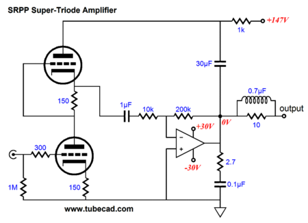
he went on to say that CCDA and Akido versions would probably make better use of the second triode (or second, third and fourth in the case of Akido).
Last edited:
That is indeed better use of a triode.. . . Akido versions would probably make better use of the second triode (or second, third and fourth in the case of Akido).
a properly designed mu-follower would also work wonderfully here, if given a really good tube like 6922: it offers plenty of current, plenty of PSRR, preserves a real triode sound signature (it's not push-pull) and shows remarkably low distortion. also a budget version with only one valve triode, replacing the upper triode, with cascoded DN MOSFETS, taking the output from the mu point (lower MOSFET), could actually do even better on the other fronts (by virtue of presenting a virtually infinite plate load impedance) IF the PSU was good enough that the loss of PSRR wouldn't matter (shunt regulated, for example). by now i think i may have veered off topic. sorry about that.
Last edited:
I could make a long post in response, but I tried that and found out there were still only 4 things to say.
1). A mid-fi driving a hi-fi will not work acceptably; however, you have proposed a hi-fi driving a mid-fi and that should work perfectly as well as achieve better performance and a lovely tone. The typical sonic signatures of the 6922 and TDA7293// are opposites and the 6922 is typically a hi-fi piece. That's good news.
2). Be sure to choose a tube that has an optimal voltage range at slightly lower than your TDA7293 because filters make a voltage drop and you'll be needing to exploit the lovely sound of cleaner power (a mid-fi amp can do a passable amount of hi-fi when run on cleaner power--see post#30's note on functional parameters whereby the minimum cost is schottky diodes ever so simply plugged into the power vias). If the 6922's optimal voltage is higher than 6N3P, then Tung-Sol 2C51 could possibly be worth consideration. My knowledge of tubes is extremely limited so I don't know the answer to the optimal voltage question. But, I have experienced that tubes and fets are every so tweaky on power voltage so it would be good to choose parts that are optimal within the ballpark of the available voltage.
3). The "one hit rule" is that a hi-fi system can take a single (and careful) hit and not suffer performance wise. You've already spent that one hit on no-ballast parallel fet outputs with TDA7293 chips, and so the remainder of the system will take extra care and labor. At this point, and with your proposal, hi-fi is not impossible and lovely tone is quite likely (the only reason to take a hit--same as the only reason to use a mid-fi--a practical useful tone that remains both beautiful and powerful, all the way to full blast), so extra care is necessary in this case.
4). No-ballast parallel fet output devices (no matter if chip or discrete) are for use in special conditions when maximum lively dynamic impact is considered more important than sending distortion into ballast resistors (to remove distortion at some cost to dynamic power--we didn't do that); and, in this case, a no-ballast paralleling of fet output devices means that your project is suited to party sound, and our 90W is suited to a great-room style house or small pub for replay of authentic concert sound. That is the capacity. I hope that your expectations do happen to fit within the capacity of the components used.
Actually, there was more to say. . .
P.S.
A lovely tone can be a good thing; however, for your health there may be a caveat since you won't be especially tempted to turn it down. SO, please stay well away from the speakers when this project is operating at full tilt and don't use it in small rooms. Not even once should you get within 20 feet of a speaker while this project is at full blast, and even then, not for longer than 15 minutes.
P.P.S.
See also the Signetics, Raytheon or Philips NE5534 low gain preamplifier (with the character and usage of a buffer) at Decibel Dungon. This could be quite useful when the TDA7293 has been used in inverting mode so that the optimal gain setting (very laborious to find it practically because you'll be trying Every value of gain divider resistors AND input load as well) is going to be lower than 38X, and the lower gain available in inverting mode *can* give you better imaging (assuming that you've also added clean power, as a prerequisite, of course). The last authentic production of that chip was circa 1996, so if using a fake, such as a TI NE5534, biasing of the output is either not suitable or can be accomplished like any other "Jelly Bean" class op-amp by running a pair in parallel with ballast resistors at output. . . but not with the transistor arrangement shown at Decibel Dungeon (because that schematic is exclusive to Signetics/Raytheon/Philips authentic chips). Anyway, since your inverting amp reaches optimal practical gain at a lower amount, in order to boost imaging performance, at the expense that a computer sound output can't drive it to full potential (without causing the source to distort), I suggest that the Decibel Dungeon "buffer with gain" project is suitable. That produces the desirable outcomes of slightly more gain and the "Bass Slam" of a good buffer as well as some build simplicity. If the circa 1996 or earlier parts are hard to source, know that the current production TI NE5534 has already been proofed by some constructors, without biasing the output and it produced the desirable results quite simply. It does at least show that cleaner power is a major factor to consider wherever there is gain.
EDIT:
It has occurred to me that perhaps the above comment and all of the parts may be useless if the TDA7293 is used with datasheet sample component values, which do get it up and running just barely and aren't optimized (the datasheet shows the standby circuit correctly, but nothing else is optimal).
P.P.P.S.
The SSA project has more to offer as for flexibility in a wider variety of tasks, and that means imaging. Well, before considering adding tubes to your chip amplifier, I think that you should be considering a finer discrete amplifier instead. The labor is probably not different, so it would be good to start in the right place. If the chip amplifier doesn't perform as needed for your goals, adding a tube won't be effective. Yes, the prospect is workable, but a fundamental error is not going to produce desired results at endpoint.
Last edited:
a few thoughts:
having several linestage amps here it seems like i have tried just about everybody's favorite opamp circuit. but to my ears, the ugly clipping behavior and excess of third harmonics over second harmonics grate on my nerves. mostly i like a 2, 3 or 4 parallel 6922 topology with no signal-path electrolytics that's largely along the lines of Conrad Johnson's high-end stuff (the ART used 5 paralleled while the cheaper -- $3,000-6,000 stuff use just one but add a Pass-esque MOSFET buffer to take the load off it -- sorta like tacking a Moosefet onto a Pete Millett common cathode valve stage).
two 6922 in parallel gets Rp down to 1400 ohms and four gets it to 700. If active loaded it get even better and provides PSU isolation from an already very quiet shunt regulated supply. swinging 20-25 V on the output is a cakewalk so saturation and/or clipping just ins't going to happen but even it did, it's sweet and creamy like great valve guitar amp. i've heard some great 6CG7s too but that usually entails a very expensive transformer because of the higher Rp.
there are low B+ (24V) derivatives of the 6922 but even the original is pretty happy at 90V-200V (ie: as low as +45 to -45 rails) so it's not hard to work with.
all that said i have heard some good (to my tender ears) solid state linestages. Nelson Pass has some good MOSFET stuff and I've heard some good 2sk170 JFETs too that put Russian PIO caps to good use. As you can see, I'm not averse to NOS stuff that would not be acceptable in a commercial product.
PS to my ears a hybrid works out ok IF the valve linestage goes well into saturation long before the solid state power amp runs out of headroom. since solid state is inexpensive just buy 4-5x the watts you actually need -- sorta like the Jeff Rowland model 10 idea or CJs MF2550 MOSFET power amp.
Last edited:
also -- here is an interesting article about one DIYer's effort to mimic the ART's qualities with JFET and MOSFET cascoded.
The SSTART Preamplifier Why on earth would anyone do such a thing? Article By Grey Rollins
with a better MOSFET (one meant for audio) and a quieter JFET (2sk170?) this topolgy might be decent to drive a chipamp.
the topology isn't really like the ART but more like CJ's low-priced stuff like the ET3
one sidenote: despite what he says, there are good current production 6922s at reasonable prices and unless you abuse them 10,000 hours life is the norm for them, and much more if run at 6.0 V (heater) instead of 6.3.
Last edited:
Gregg van der Sluys, Classic Valve Design, MooseFet preamplifier with a specific make of IRF710, sounds just like 6922, big, clear, high resolution and not bright (if you want bright, plug in cheap IRF510). There are also three dials to use for tweaking the sonic signature however you like.
P.S.
Same is true of the chip amp. It is potentially important to tweak the power amplifier's gain divider values for best stability (aka sonic signature, aka tone). This labor is sketchy enough that fixed resistor values probably won't be optimal, so you'd need a multi-turn trimmer to get it precisely. With such a vast capacity (nearly any variety of sonic signature desired), it *may* be ironically goofy to add a lot of tubes when the chip amp is set on datasheet suggested values with its real capacity gone unused. Just sayin. 🙂
it *may* be ironically goofy to add a lot of tubes when the chip amp is set on datasheet suggested values with its real capacity gone unused. Just sayin. 🙂
yep, i've come to that same conclusion --- except for LM3886. keeping the loop areas small, and keeping the drive low enough so the abominable spike monster doesn't rear it's head, it works way above its grade level. it was not out of place, for example, in the Jeff Rowland Model 10.
For the LM3886, try (search) the accessory named "LTP Soft Clipper" which is especially effective if using very low capacitance diodes, such as bat86 or whatever low capacitance diode that the latest model of Honey Badger uses for its clip behavior limitation. The extremely simple and inexpensive ltp soft clip circuit will probably work on your LM3886 to clip the inputs before the spike system could activate. Use the lowest capacitance diodes available and a multi-turn trimmer.
I'd also like to mention that the TDA7293 and LM3886 are so extremely different that ideology and accessories for one will result in poor performance for the other, and that is because they're different.
At Post1 and post30, this particular TDA7293, if built as specified, maintains a useful output when used abusively beyond rail capacity and so doesn't need the LTP soft clip accessory.
However, a "slow compressor" of at least 15ms (during which full power clipping AND likewise maximum bass dynamic impact is allowed) may be used and can be especially attractive if dual asymmetric design (either 2 optos or 2 jfets per each channel--don't clip the upswing when the downswing exceeds) because music is strongly asymmetric and forced symmetry is the least harmful modification for enhancing headroom. Also for fet outputs, like the TDA7293 and similar discrete amplifiers, the peak output is usable (without corrupting the outputs) if also limited to a very short timeframe. The concept is also useful to the power supply, since after the momentary epic blast, the output level shift (to less) is useful to recoup the supply to a full charged condition (if quite sturdy) resuming high quality output instantly.
That concept is not well exploited with BJT output amplifiers (like LM3886, and similar discrete amplifiers) whereby abusive peaks cause cumulative damage to the output device's internal insulating layer, eventually resulting in a short out. Well, they're really very different; so, an optimized build would accommodate the differences. Even so, the #1 way to blow a chip amp is overcurrent the input as advised by the datasheet schematic's example resistor values. Well, that's ironic.
Last edited:
If I read the LM3886 data sheet correctly the inputs seem almost indestructible with a max. voltage of 60V and a very low max. current 0.2 uA. I am convinced that most failures are caused by bad tab insulation.
I don't know for the TDA7293.
I don't know for the TDA7293.
- Home
- Amplifiers
- Chip Amps
- TDA7293 Parallel kit from ebay (modular/slave style, no lossy emitter resistors)