Thanks. I hadn't seen the bit in red at 2us, 5v (500kHz)
I had seen the large bit in blue at 0.5us, 5v (2MHz), and the two small bits in blue at 2.2v and 2.5v
And I am measuring 5.1v, 44kHz
I do not see how all five of those things cannot be true simultaneously, though I will allow that 2.2v or 2.5v could be the average voltage seen by a voltmeter of a squre waveform at 5v
The resistor in the SL-PC740A is replaced with an RC to GND in the SL-PS700, otherwise the same.
I'm open to the hypotheses that
1/ I've soldered a lead to the wrong pin
2/ I'm creating a short to another signal
3/ The SPDIF of my 6626 is broken, possibly by me soldering on it.
😀😀😀😀😀😀😀😀😀
😀😀😀 It's alive 😀😀😀
😀😀😀😀😀😀😀😀😀
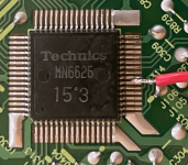
Hypothesis #1 was valid - I had soldered to the wrong pin!
So. The answer is spectacularly simple.
Connect pin #23 [TX] of a 1980s MN6626 and [GND] to an RCA cable and shove that into the coax digital input of a 2023 hifi, and it all works!
No convertor boards.
No resistors.
No capacitors.
I need to tidy it up a little - do remember that I'm using a cracked Panasonic SL-PC364 as a test mule for my two pristine Technics SL-PC705, so have bits hanging off, hanging out, cracked, scratched, bent, rusty, and all sorts.
The elegant solution will be to repurpose a 3.5mm socket originally designed for the Tape Synchro Edit or the wired remote, and use a 3.5mm to RCA cable to connect to the hifi.
Celebratory picture of SPDIF trace 😀
The MN6625 and MN6627 of the same era also have a [TX] pin, and similar circuit diagrams, so likely work the same way
Thanks @huggygood for the nudge to look for an existing output.
Tidied it up so all modifications are internal. Did not need to modify the chassis.
Total modifications are
1/ Cut through the three circuit board tracks going to the three pins of the [SYNCHRO EDIT] 3.5mm external socket
(surprisingly, none of those three pins went to [GND])
2/ Connect the [SYNCHRO EDIT] socket pin that you think should be [GND] to [GND]
3/ Connect a lead to pin #23 [TX] of the MN6626
4/ Connect the other end of that lead to the [TIP] and [RING] pins of the [SYNCHRO EDIT] socket.
Everything above is in the photographs.
After doing that, I decided I didn't want both [TIP] and [RING] live, so disconnected one, and did not take a new photograph.
A 3.5mm -> 2x RCA lead now carries the SPDIF signal to my hifi. One of the RCA jacks is live, and one is dead. Much better than both being live.
I should insert a coupling capacitor in that line. I'm thinking that for a ~2MHz signal, a ~500pF capacitor will be good. Any builds?
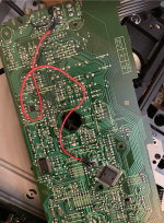

I've now converted three CD players. SL-PC364; SL-PC705 115v; SL-PC705 110/120/220/240v
2nd & 3rd conversions were tidier than the first, so I add tidier photos.
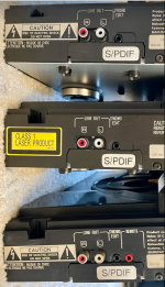
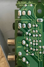
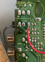
Why would I want THREE?
I don't. I want two.
2nd & 3rd conversions were tidier than the first, so I add tidier photos.
- I used the [SYNCHRO EDIT] 3.5mm socket in all three conversions.
- The SL-PC364/505 also has a [REMOTE] socket that is absent on the SL-PC705.
- Doesn't matter which socket is used.
- Only need to scratch through the [TIP] and [RING] circuitboard tracks.
- Only need to connect the [TX] pin from the MN6626 to either [TIP] or [RING], not both.
- Still connected the [GND] pin to [GND], regardless whether the track is scratched or not.
- To be fair, I didn't test if this was necessary. The circuitboard connects the [GND] pin to [GND] with an RC arrangement.
- I printed and applied an S/PDIF sticker to each case 🙂


Why would I want THREE?
I don't. I want two.
- The SL-PC364 is an ugly, cracked, test mule.
- One SL-PC705 sits on my office desk and can now connect to a headphone amp with digital-only inputs
- The other SL-PC705 sits in my living room can now connect to a miniDSP Flex that has digital-only inputs.
the good question is "why not ?" and not "why ? " 🙂Why would I want THREE?
I've received some private questions about this modification.
All the similar CD changers of which I am aware are
All three decks I modified are the gen3 models using the MN6626 DSP (pin 23).
I expect a similar modification with the gen2 models using the MN6625 DSP (pin 17) would work.
I suggest avoiding the models without lids (11, 14, 503) as they'll contain 30+ years of dust.
Most units that are remote capable (20, 25, 45, 705) are sold without a remote. I bought one separately for $10.
The gen1 & 2 models have a slight bias for right-handed users.
Beyond that, they're all functionally equivalent, and will sound the same through S/PDIF, so choose a unit based on appearance, colour, availability, and condition.
The lids scratch very easily. This polishes out with Novus 3 plastic polish, then to a high gloss with Novus 2.
Cracks do not polish out. Obviously.
Ask eBay sellers to wrap units in kitchen cling film before shipping to prevent more scratches.
Several units are listed a powering on but not reading discs.
Of the three I bought, one worked fine; one needed two new drive belts ($7 for 100 belts); one needed the laser lens wiping with IPA.
I suspect most units that turn on and do not play just need one of the fixes above.
An eBay search term for all at once would be "sl-pc (10,11,14,15,20,25,45,505,505,705,363,364)", e.g.
eBay.com link to all CD changers above
eBay.co.uk link to all CD changers above
All the similar CD changers of which I am aware are
| Model | Brand | Gen | Lid | Display LEDs | Handed | Feet | Carousel | Remote | DSP |
| SL-PC10 | Technics | 1 | black & smoke | light green | right | silver | black | no | MN6625 |
| SL-PC11 | Technics | 1 | no | light green | right | black | black | no | MN6625 |
| SL-PC20 | Technics | 1 | black & smoke | light green | right | silver | black | yes | MN6625 |
| SL-PC14 | Technics | 2 | no | light green | right | black | black | no | MN6625 |
| SL-PC15 | Technics | 2 | smoke / domed | light green | right | silver | black | no | MN6625 |
| SL-PC25 | Technics | 2 | smoke / domed | light green | right | silver | black | yes | MN6625 |
| SL-PC45 | Technics | 2 | smoke / domed | light green | right | silver | black/silver | yes | MN6625 |
| SL-PC363 | Panasonic | 2 | smoke / flat | orange | right | black | black | no | MN6625 |
| SL-PC503 | Technics | 3 | no | light green | ambidextrous | black | black | no | MN6626 |
| SL-PC505 | Technics | 3 | smoke / domed | light green | ambidextrous | silver | black | no | MN6626 |
| SL-PC705 | Technics | 3 | smoke / domed | light green | ambidextrous | silver | black | yes | MN6626 |
| SL-PC364 | Panasonic | 3 | smoke / flat | orange | ambidextrous | black | black | no | MN6626 |
All three decks I modified are the gen3 models using the MN6626 DSP (pin 23).
I expect a similar modification with the gen2 models using the MN6625 DSP (pin 17) would work.
I suggest avoiding the models without lids (11, 14, 503) as they'll contain 30+ years of dust.
Most units that are remote capable (20, 25, 45, 705) are sold without a remote. I bought one separately for $10.
The gen1 & 2 models have a slight bias for right-handed users.
Beyond that, they're all functionally equivalent, and will sound the same through S/PDIF, so choose a unit based on appearance, colour, availability, and condition.
The lids scratch very easily. This polishes out with Novus 3 plastic polish, then to a high gloss with Novus 2.
Cracks do not polish out. Obviously.
Ask eBay sellers to wrap units in kitchen cling film before shipping to prevent more scratches.
Several units are listed a powering on but not reading discs.
Of the three I bought, one worked fine; one needed two new drive belts ($7 for 100 belts); one needed the laser lens wiping with IPA.
I suspect most units that turn on and do not play just need one of the fixes above.
An eBay search term for all at once would be "sl-pc (10,11,14,15,20,25,45,505,505,705,363,364)", e.g.
eBay.com link to all CD changers above
eBay.co.uk link to all CD changers above
Typo
An eBay search term for all at once would be "sl-pc (10,11,14,15,20,25,45,503,505,705,363,364)", e.g.
eBay.com link to all CD changers above
eBay.co.uk link to all CD changers above
An eBay search term for all at once would be "sl-pc (10,11,14,15,20,25,45,503,505,705,363,364)", e.g.
eBay.com link to all CD changers above
eBay.co.uk link to all CD changers above
OK, third error. I wish I could edit my post, but I can't.
The gen1 models (10,11,20) do not have a 3.5mm socket to utilise.
You can either add one, or, better still, add an RCA socket and use a single RCA-RCA cable.
Or add an optical Toslink socket if you're feeling fancy. In addition to ground and signal, you would need to add a ~5v connection. There are plenty available on the circuit board.
Bringing some "random" knowledge from a Hungarian Facebook group here, maybe useful for others too.
Solution is not mine. Author inspired by this Lampizator article.
Topic is getting AES-EBU digital out from a Technics SL-PG360A CD Player - it works for him, driving a 15m cable and some modern well-measuring DAC.
According to him, the resulst are stunning.
My player is an SL-PG100 and he told me most of his technique might be applied to other CD players from Technics too, which all share the same basic design.
Hopefully useful, partly or as a whole. Trying to translate his comments correctly.
Enjoy.
-----------------------------------------------------------------------------

Smaller screws might fit better here.

XLR used, he doesn't like RCA. Coaxial connection was prone to interference but since the DAC accepts AES-EBU balanced signal, it was the most convenient solution. Totally immune to noise, interference, whatsoever. For those who stick to RCA out, the real and proper connector type would be BNC.
Small DIP transformer for the next section:


The small transformer is from eBay, type PULSE DIP-4 PE-65612NL.
Secondary is in series with a 75R resistor and 2.2nF cap, for blocking DC. Values aren't critical here, he could only find these quickly.. they do the job.
Here you can't see the secondary side but there he put a parallel resistor of 110R in order to reduce reflections.

The player opened. Almost empty, even quite some space for a proper headphone amp but definitely plenty of space for any kind of extra connector(s).

It was difficult to find out where SPDIF is coming out from. If we manage to find it, it can be sent then to coaxial, optical or AES-EBU interfaces.
In case of the SL-PG360, digital signal can be found at pin 17 of connector CN401. Pin 15 is GND.
A small shielded signal cable was used to lead it to the back side of the chassis where the RC+transformer circuitry was made.
That's it.
Regarding format, it's S/PDIF, signal level and impedance is AES-EBU. And it works like a charm.
Solution is not mine. Author inspired by this Lampizator article.
Topic is getting AES-EBU digital out from a Technics SL-PG360A CD Player - it works for him, driving a 15m cable and some modern well-measuring DAC.
According to him, the resulst are stunning.
My player is an SL-PG100 and he told me most of his technique might be applied to other CD players from Technics too, which all share the same basic design.
Hopefully useful, partly or as a whole. Trying to translate his comments correctly.
Enjoy.
-----------------------------------------------------------------------------
Smaller screws might fit better here.
XLR used, he doesn't like RCA. Coaxial connection was prone to interference but since the DAC accepts AES-EBU balanced signal, it was the most convenient solution. Totally immune to noise, interference, whatsoever. For those who stick to RCA out, the real and proper connector type would be BNC.
Small DIP transformer for the next section:
The small transformer is from eBay, type PULSE DIP-4 PE-65612NL.
Secondary is in series with a 75R resistor and 2.2nF cap, for blocking DC. Values aren't critical here, he could only find these quickly.. they do the job.
Here you can't see the secondary side but there he put a parallel resistor of 110R in order to reduce reflections.
The player opened. Almost empty, even quite some space for a proper headphone amp but definitely plenty of space for any kind of extra connector(s).
It was difficult to find out where SPDIF is coming out from. If we manage to find it, it can be sent then to coaxial, optical or AES-EBU interfaces.
In case of the SL-PG360, digital signal can be found at pin 17 of connector CN401. Pin 15 is GND.
A small shielded signal cable was used to lead it to the back side of the chassis where the RC+transformer circuitry was made.
That's it.
Regarding format, it's S/PDIF, signal level and impedance is AES-EBU. And it works like a charm.
Last edited:
For my SL-PG100, an interesting article (measurements from ASR).
And his suggestions for the SPDIF-out:
Coupling caps are 1-10nF (here he used 2.2nF, works fine).
Probably not only the SL-PG360A and the SL-PG100 share the same design but some other CD players from Technics of this era too.
And his suggestions for the SPDIF-out:
- signal is generated by the IC MN6626 and appears on pin23
- it luckily also arrives to the connector CS702, unsurprisingly onto pin17. GND is pin 15. Same like above. Easier to solder here than on the IC itself.
- through a resistor divider network and capacitor it's ready to be sent to an RCA connector (BNC more ideal).
- or we can go XLR through a small signal transformer or 74HCU04 inverters, for driving AES-EBU cable
- or for optical output as a LED driver
- protocol is the same, only signal levels differ
Coupling caps are 1-10nF (here he used 2.2nF, works fine).
Probably not only the SL-PG360A and the SL-PG100 share the same design but some other CD players from Technics of this era too.
Regarding format, it's S/PDIF, signal level and impedance is AES-EBU. And it works like a charm.
After a monster long summer and doing outdoors stuff, the weather has gone cold, so I am looking at my SL-PC705 again.
The springs are no longer strong enough to support the lid.
They do push out of the hinges fairly easily (by dangerously pushing through the slot in the back with a jeweller's screwdriver).
20mm long, 8mm OD, 4mm ID.
No idea what the spring rate is and have not yet measured it, because...
...all I would learn is the current strength of an out-of-spec spring that is insufficient, and...
...20x8x4mm die springs are readily available marked as very light, light, medium, heavy, very heavy duties, not marked numerically, and...
...because I found for $15 on Amazon a box of 50 die springs, in a range of duties, all 20x8x4mm
Should arrive by the weekend, then a bit of touchy-squeezy and trial-and-error will either result in success, failure, broken hinges, broken lids, or some combination thereof.
Yeah, well that didn't work entirely well.
Springs arrived. Clearly a different size to the originals.
Checked with my caliper... which has turned into a random number generator. It does that just before the battery dies.
Real size of the originals is 15mm, 8mm OD, 4.5mm ID.
15x8x4 exists for sale, but not as ubiquitously as the 20x8x4, and certainly not 50 for $15.
Good news is that matching spring rate is reasonably easy. The rate of the spring marked Green/TH/Heavy is about 9% stiffer than the original, which has gone soft.
New springs should arrive Tuesday.
Springs in. Perspex/Plexiglass lid now stays up.
Dimensions: 15mm long, 8mm OD, 4mm ID
Spring rate: TH/Green/Heavy Duty
$6 for a pair on Amazon, listed as die springs or mould springs.
For completeness, the ID of the original spring is more like 4.8mm, and of the replacements more like 4.2mm, but whatever.
With only one spring replaced, and one original, they were not strong enough to support the lid.
With both replaced, works great.
I did invent a few new swearwords getting the new springs into the hinges.
Ultimately I did it by putting a cable-tie / zip-tie through the spring lengthwise, compressing with pliers, and tightening the tie to hold the spring compressed.
Push the spring half way into the hinge, cut the tie and pull it out, then push the spring the rest of the way in.
Certainly need eye protection while doing that.
- Home
- Source & Line
- Digital Source
- Technics CD Player - locating I2S signals for DAC upgrade?