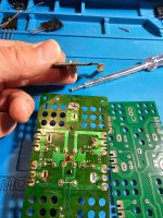
Here are some more pictures of my very difficult restoration. 🙂
Attachments
-
 20250403_231346.jpg698.5 KB · Views: 26
 -
 20250403_144000.jpg547.9 KB · Views: 21
 -
 20250403_143958.jpg536.4 KB · Views: 20
 -
 20250403_143954.jpg486.2 KB · Views: 22
 -
 20250403_142403.jpg813.1 KB · Views: 23
 -
 20250403_142353.jpg935.7 KB · Views: 24
 -
 20250403_004554.jpg729.9 KB · Views: 19
 -
 20250403_004541.jpg735.5 KB · Views: 20
 -
 20250402_003037.jpg619.3 KB · Views: 23
 -
 20250401_232614.jpg721.1 KB · Views: 24
Hehe, don’t laugh at me too much. 😅
Take a closer look at the pictures up there… and you’ll notice the mistake.
It happens :-(
Now I have to take everything apart again… oh man.
Take a closer look at the pictures up there… and you’ll notice the mistake.
It happens :-(
Now I have to take everything apart again… oh man.

It looks difficult to work on
It is however after you disassemble it and put it back together couple of times you already know the tricks how to handle it 🙂
47Ohm. Deem
Looks like 4,7 Ohm to me.
Not yet... I need to buy new resistors first.So is it fixed now?


One more question for you experts out there…
I replaced both original, brand-new FETs:
µPA68H - L
with new µPA68H - K.
Does this letter difference actually cause noticeable distortion in sound?
The service manual says:
Transistor, Input Differential Amplifier
(Use in ranks L or M) [FET]
So, it should be replaced with L or M versions.
But L or M are nowhere to be found.
Should I rather keep the original L versions, even if they’re old?
Attachments


In FET's those type of letters often denote Idss which is the drain current at zero gate/source bias voltage.
If that is so then you have to assume the original spec is going to be the best even others seem to work. No reason to suspect the older parts unless you have evidence to the contrary (such as they are actually known to fail or deteriorate)
If that is so then you have to assume the original spec is going to be the best even others seem to work. No reason to suspect the older parts unless you have evidence to the contrary (such as they are actually known to fail or deteriorate)
Why did I decide to replace them??
On one channel, the distortion was raised at the 3rd harmonic.
Now I don’t know if those overly strong resistors in the bias circuit are also to blame for this…
If it gets worse, I’ll put the original old FETs back in.
On one channel, the distortion was raised at the 3rd harmonic.
Now I don’t know if those overly strong resistors in the bias circuit are also to blame for this…
If it gets worse, I’ll put the original old FETs back in.
What do you think? Can we replace this burnt foil with self-adhesive aluminum foil?
It's a heat-resistant aluminum foil.
I think the light would reflect better than it does now. With the new lights, it seems too dark to me.
What do you think?
It's a heat-resistant aluminum foil.
I think the light would reflect better than it does now. With the new lights, it seems too dark to me.
What do you think?
Attachments


I don't know what that relates to tbh 🙂 We've gone from biasing and FET's to ? Don't know what you are referring to with that foil.
No problem…
Here’s the update: I’ve replaced the resistors, and things have improved nicely.
The bias now also stays low.
After 1 hour of warm-up, I set the bias to 30 millivolts, and it’s holding steady.
I’ve adjusted the DC offset to 0.000V on both channels.
Later today, I’ll also try a test with a 4-ohm load to see how far it can go.
I’ll probably put the original FETs back in…
Everyone says that the ones marked with an "L" were made more precisely back in the 1980s.
But I don’t even know how I would measure them, since I don’t have the equipment to test FETs…
As for the light, I asked if anyone has ever replaced the original burnt foil with a different one…
Last edited:
- Home
- Amplifiers
- Solid State
- Technics SE-A3 bias adjustment