a pentode triode strapped is a triode.....
the is an amp i did using 16 kt88's....
i found out that no gnfb was ever required....
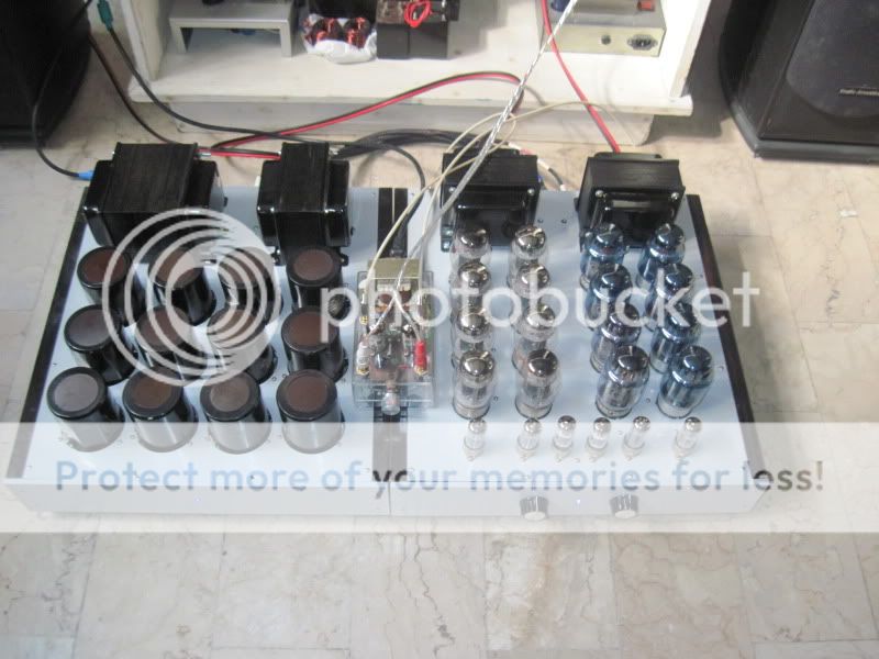
You have to turn on the air conditioning when you use this amp!!!!
What OPT you use here?
"How does the diode make the difference, it's only 0.7V drop. "
You will get various opinions as to what or whether that diode is doing anything. But one useful feature is that it can make the tube more immune to catastrophic failure. George (Tubelab) found that if the screen grid gets overheated and is at a lesser voltage than the plate, it can start emitting electrons furiously to the plate. The diode would stop that. (George is experienced at making tubes go flash-boom at obscene power levels.)
You will get various opinions as to what or whether that diode is doing anything. But one useful feature is that it can make the tube more immune to catastrophic failure. George (Tubelab) found that if the screen grid gets overheated and is at a lesser voltage than the plate, it can start emitting electrons furiously to the plate. The diode would stop that. (George is experienced at making tubes go flash-boom at obscene power levels.)
Last edited:
"How does the diode make the difference, it's only 0.7V drop. "
You will get various opinions as to what or whether that diode is doing anything. But one useful feature is that it can make the tube more immune to catastrophic failure. George (Tubelab) found that if the screen grid gets overheated and is at a lesser voltage than the plate, it can start emitting electrons furiously to the plate. The diode would stop that. (George is experienced at making tubes go flash-boom.)
can not see the need for it, so i do not do that, a resistor is all it takes to triode strap a tetrode or pentode...
in this day and age of the internet, there are as many blah-blah going on as there are gold of informations...
Kevin Carter - K&K Audio, the U.S. Distributor for Lundahl transformers.
I think it has more to do with the fact that it is a diode and not the voltage drop.
Tracy
This links to some of my projects. The references to my KT120 mono-blocks are not quite up to date. They don't show the new output cathode current sinks and some other changes I made to improve heat dissipation. The amps originally used 6550s and less B+.
Having the diode makes the screen stop conducting if the plate were to become more negative than it. I don't know personally what that does to make it act more triode like. Perhaps in a situation were the plate dips lower than the screen, the screen abruptly begins to conduct more and creates a blip in the transfer curve or something to that effect. It will of course provide a measure of protection to the screen in these cases. I suppose someone who does inductive loading for a living might know a thing or two.
hhhmmm, a screen that stopped conducting makes a plate that stops conducting current...
do we want this in our amps?
do we want this in our amps?
"How does the diode make the difference, it's only 0.7V drop. "
You will get various opinions as to what or whether that diode is doing anything. But one useful feature is that it can make the tube more immune to catastrophic failure. George (Tubelab) found that if the screen grid gets overheated and is at a lesser voltage than the plate, it can start emitting electrons furiously to the plate. The diode would stop that. (George is experienced at making tubes go flash-boom at obscene power levels.)
can not see the need for it, so i do not do that, a resistor is all it takes to triode strap a tetrode or pentode...
in this day and age of the internet, there are as many blah-blah going on as there are gold of informations...
The fellow who should get the credit for coming up with this is probably Dennis Grimwood. He's had a page on it for years.
AJT Yeah, I hear you. The bs online is tiring but I'd remind you that half the crap sold online is posted by guys who've never actually tried what they're recommending. In this case it's a 10¢ part that takes a couple of minutes to insert into the circuit. The difference is easy enough to hear though whether you think it's an improvement or not is up to you, of course.
i am one such guy that once happy with a setup, i do not tinker with it anymore than i have to.....but who knows?.....i am open to possibilities, may be one morning i might wake up wanting to do it...😉
oh, i am sure smoking amp has something to say....hope he chimes in....😉
The fellow who should get the credit for coming up with this is probably Dennis Grimwood. He's had a page on it for years.
oh, i am sure smoking amp has something to say....hope he chimes in....😉
Even if he remains silent I'm sure he has more to say than I ever will! 😀
Did you notice the link?
Did you notice the link?
yes...and i know smoking-amp's comment...just want him to say it...it was posted here somewhere....😉
clue: ever wondered why not many are doing it?
clue: ever wondered why not many are doing it?
From Grimwoods site:
"Another and previously unpublished option to creating an operating environment where the Screen Grids will be at a DC potential sufficiently high enough to attract and accelerate electrons towards the Plates but - to maximise power output - not to collect and divert them to earth through the B+ supply, is the humble silicon diode semi-conductor rectifier.
By inserting a standard half-wave silicon rectifier diode in series with the Grid Stopper resistor, an electronic control circuit is created whereby the Screen Grid will be able to be energised at DC potential attracting and accelerating electrons towards the Plate - still electrostatically controlling current flow in the normal way - but blocking the flow of AC current from the Screen Grid back to the DC source - ie "one way traffic"
This works because the current flow in the tube is always from the Cathode to the Anode (Plate). The diode, being a semi-conductor, blocks current flow in the reverse direction, thus enabling DC current to feed it in the conventional manner but blocks AC current from passing back through it to a load.
Thus then there is no circuit formed between the Screen-grid and the load so no current can flow in the usual direction."
--------------------------------------------------------------------------
The site seems to be a bottomless abyss that one can fall into and never be heard from again. He seems to have this initially plausible idea of making the tube act like a triode by putting voltages on the intervening grids that would naturally occur in the tube's spacecharge. So the extra grids (screen and g3) effectively disappear. From there on it seems to drop off the logic map.
The diode in the screen grid idea seems to start from this patent:
http://www.oestex.com/tubes/USP3153766.pdf
Which attempts to keep the screen grid at whatever has the most positive potential (B+ or plate). So it follows the plate V between B+ and positive swinging plate (but not negative swinging plate). This has got to be rather distortive with the sudden voltage switchovers.
But the single diode in the screen feed doesn't do that anyway. It doesn't really seem to do much of anything................... (except protect from catastrophic meltdown when the screen gets hot enough to emit electrons towards the plate)
It seems that he wants the screen to have its (UL) supply voltage, but doesn't want it to drive any current into the OT (or suck any current out of the cathode to plate stream). But that's not what the diode does. One could put a Mosfet follower there, it's gate driven from the UL tap. Source connected to the screen grid. And drain supply from some extra high B+ supply. But even that does not stop the screen grid from harvesting (and then wasting) some cathode current. However, the idea of making the screen grid track the space charge voltage (a special kind of UL, see below), would probably cause it to extract a constant percentage of plate current. And that would avoid distortion effects.
The special kind of UL needed would be a (approx. 40%) divider from the plate down to ground (cathode) potential, instead of the usual UL tap from plate to B+. This prevents the plate V from ever descending below the screen V. This also will lower the power output quite a bit since the screen V gets very low when the plate is trying to draw the most current. You want linearity, get no power.
Last edited:
clue: ever wondered why not many are doing it?
Heh heh, I have no idea. For my part, I saw his page years ago at the time I was first starting to play with triode strapped pentodes, and I found that adding the diode could make a difference I could hear and liked. That's all, no big deal. (It's a ten cent experiment!)
Merry Christmas, I am too full and have too much drinks to talk. I am having too much fun with my little grand daughter.
Sorry, I should credited Mr. Grimwood. I could not remember his name. Kevin sent a link to his postings many years ago when I was playing around with an old Eico HF-89. I tried it then and liked the results.
The diode in the screen circuit was mentioned, and even required, in some application notes published by Eimac in reference to operating their RF tetrodes in linear RF amps. A tetrode can exhibit a negative resistance region whereby the screen current can reverse itself under certain load conditions. Under this type of operation nonlinearity and possible tube damage can occur. Much of this does not apply to a conventional audio tube in an audio amp. The negative resistance region is very small or non existent in a pentode.
I first read the works of Grimwood and his optimized electron flow stuff about 10 years ago. I even connected up an EL34 and tried some of his circuits. It seems that Grimwood forgot the reason for the suppressor grid. The suppressor grid was added to the tetrode tube to reduce or eliminate secondary electron emission from the plate. High energy electrons could hit the plate hard enough to dislodge other electrons which were attracted to the screen causing an unwanted current flow path. This creates the negative resistance region and the "tetrode kink". A third grid with a negative charge (compared to the screen) repels these electrons back to the plate.
Operating the suppressor at a large positive voltage makes the kink worse, and the diode may be needed to avoid meltdown under certain conditions. Wire it all up and graph the curves.....not pretty.
My experiments at the time were using pure screen drive, and yes I blasted a few tubes into oblivion by driving the screen grid positive at the same moment the plate is near zero. This is the flaw in pure screen drive at high power. The diode will prevent the tube arc that follows the glowing screen grid, but will not prevent the glowing grid.
The diode in the screen grid on a normal audio amp does not seem to have much of an effect in simulation, measured performance, or listening tests on an amplifier operated below clipping. It does have some effect on an EL34 design operated well into clipping (a cranked guitar amp)
I first read the works of Grimwood and his optimized electron flow stuff about 10 years ago. I even connected up an EL34 and tried some of his circuits. It seems that Grimwood forgot the reason for the suppressor grid. The suppressor grid was added to the tetrode tube to reduce or eliminate secondary electron emission from the plate. High energy electrons could hit the plate hard enough to dislodge other electrons which were attracted to the screen causing an unwanted current flow path. This creates the negative resistance region and the "tetrode kink". A third grid with a negative charge (compared to the screen) repels these electrons back to the plate.
Operating the suppressor at a large positive voltage makes the kink worse, and the diode may be needed to avoid meltdown under certain conditions. Wire it all up and graph the curves.....not pretty.
George (Tubelab) found that if the screen grid gets overheated and is at a lesser voltage than the plate
My experiments at the time were using pure screen drive, and yes I blasted a few tubes into oblivion by driving the screen grid positive at the same moment the plate is near zero. This is the flaw in pure screen drive at high power. The diode will prevent the tube arc that follows the glowing screen grid, but will not prevent the glowing grid.
The diode in the screen grid on a normal audio amp does not seem to have much of an effect in simulation, measured performance, or listening tests on an amplifier operated below clipping. It does have some effect on an EL34 design operated well into clipping (a cranked guitar amp)
Hi All, concerning the sound and nasties of LTP tube topology (I have not experience with differential OS), I have made redesigned Jadis JA-30, which had the same schematics as here at thread http://www.ne.jp/asahi/kita/yamaneko...fler195111.pdf, with completelly flat and borring sound with no highs, to SE topology.. I think that LTP with tubes has low gain to could repair its distortion well with reasonable NFB.
Some schematics and simulations of this JA-30 circuit are here: http://perys.cz/hobby/?lang=en
Some schematics and simulations of this JA-30 circuit are here: http://perys.cz/hobby/?lang=en
Last edited:
Kevin Carter - K&K Audio, the U.S. Distributor for Lundahl transformers.
I think it has more to do with the fact that it is a diode and not the voltage drop.
Tracy
This links to some of my projects. The references to my KT120 mono-blocks are not quite up to date. They don't show the new output cathode current sinks and some other changes I made to improve heat dissipation. The amps originally used 6550s and less B+.
Wow, you put a lot of work on your amps. You selling them?


- Status
- Not open for further replies.
- Home
- Amplifiers
- Tubes / Valves
- The differential amplifier