The link of picture has died meantime. Can you attach it again ?
Thanks,
Adrian
Original File
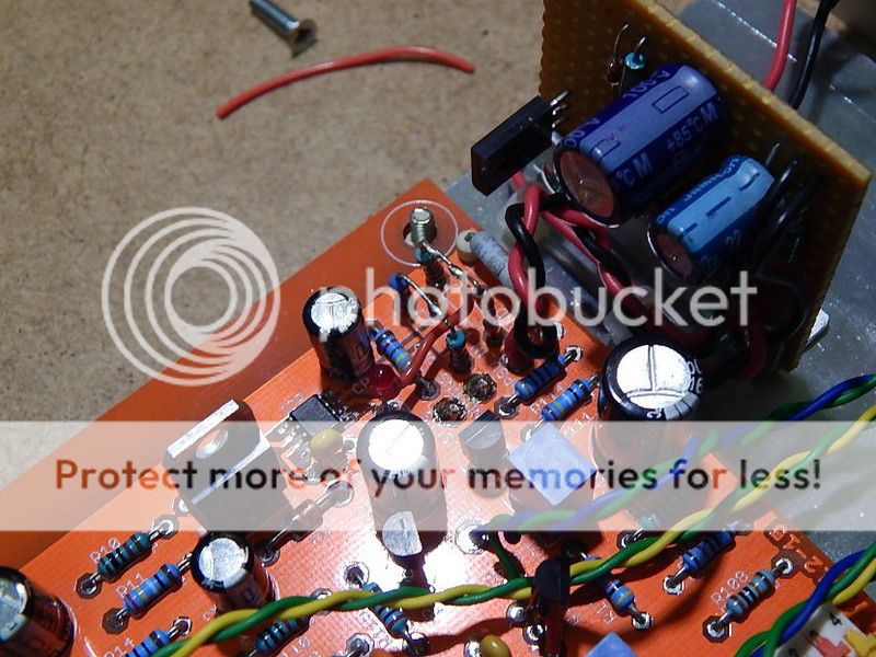
I've updated the link to show the correct component Numbers.
Sharif.
Quoting myself from post#287: <snip>"Currently my prototype is with a friend (very happy with the sound), since I'm a fan of valves and I use a pre with tubes, which sounds less dry in bass despite not measure big difference in bass THD (but different harmonic profile) or measured response. ...<snip>Installed the 100r resistors and 470uf caps. The sound is the same, same nice trebles and sweet voices but weak, dry bass
Waiting for DIYBras feedback.
Sent from my iPad using Tapatalk
Is not with me anymore but my friend lives near me and I ask if he wants a upgrade in this pre. Maybe I try the PNP output follower also.
I don't want to overly press this, but I think you should know: that voltage regulator is totally unsuitable for the circuit is it powering.
The design is fundamentally flawed.
The LED1 bias is 1.6 V. This puts the inverting terminal of the op amp 1.6 V from the negative power rail. The THS4031 op amp, however, is not rail to rail. According to the datasheet the common mode input voltage is only up to about 1.5 V from the rail. It's touch and go whether the IC will function properly or not with one input at 1.6 V. (My guess is it won't) If you go and put a rail-to-rail op amp in the circuit, like the LT1677, the whole thing goes bezerk.
That's one thing. The other is with R7=180 ohms it seems 60 mA is shunted through the MOSFET. This is just a waste since the circiut draw is barely 5 mA both channels (right?). Increasing R7 to 1k puts the shunt current at 10 mA, but it could actually be even lower since it only has to shunt the deviation in load current.
Anyway, no matter what you do the regulator output to a pulsed current load is horrible. Trying to damp it out with capacitance just makes it worse.
Attachments


Last edited:
One small further point: the shunt current is adjusted by RP1 (R7 in my quick-n-dirty sim), which means it is rather poorly controlled since I_shunt = (Vin - Vout)/RP1 and Vin (PSU_IN) is variable. Vin will change from day to day, and more importantly from build to build. What you really want there is a current source, so you can set the MOSFET bias current through independently of changes in the supply voltage.
A Lm317 used as a CCS in place of RP1 could be a solution ?
Sent from my Nexus 5 using Tapatalk
Sent from my Nexus 5 using Tapatalk
Too noisy, better use a DN2540
Even with RP1 replaced with the CCS there is still current pulsing going on.
This can't be new how do instrumentation psu over come this problem?
http://www.wenzel.com/documents/finesse.html
Last edited:
Someone has to test that for real on a build with a step load. I just wanted to caution about the 317's self noise.Even with RP1 replaced with the CCS there is still current pulsing going on.
I agree with the LM317 self nosie problems.
Would a series 48V regulated supply help before the shunt reglator?
Would a series 48V regulated supply help before the shunt reglator?
One small further point: the shunt current is adjusted by RP1 (R7 in my quick-n-dirty sim), which means it is rather poorly controlled since I_shunt = (Vin - Vout)/RP1 and Vin (PSU_IN) is variable. Vin will change from day to day, and more importantly from build to build. What you really want there is a current source, so you can set the MOSFET bias current through independently of changes in the supply voltage.
Good points about that LED and the series R. If you dont want to mutilate the PCB a good solution would be to replace the LED ref with a 2-pin 5V low noise ref like the LM4040-05 and similar (more low noise) chips.
Jan
I agree with the LM317 self nosie problems.
Would a series 48V regulated supply help before the shunt reglator?
The idea was to use a 48VDC wall wart. I am using that and no trace of hum or noise on my speaker.
Jan
Nobody is having hum or noise.
Sent from my Nexus 5 using Tapatalk
Then what is the problem we want to solve?
A Lm317 used as a CCS in place of RP1 could be a solution ?
As I see it there are two ways around it:
1. Use a rail-to-rail op amp.
2. Bias the LED and RP3 (R3 in my schema.) up away from the negative rail (i.e. ground).
Mod (2.) is enabled using two diodes as shown below. This has minimal impact on the circuit operation and should allow you to be able to just about any op amp.
Note that the circuit is still very jumpy. It needs a capacitance right next to the output or it will oscillate. Even with the capacitor the pulse response has overshoot. It's the nature of it.
Attachments

Then what is the problem we want to solve?
Unless rail-to-rail, op amps don't perform as per the datasheet when the input or output is sitting at the positive or negative rails. There is a grey area 1-2 V away where it might be OK, it might not, depending on the op amp or just sample variation.
I don't have a model to sim the op ap used in the circuit. Trying different ones in the LTSpice database, only rail-to-rail ones worked as advertised unless I biased the inputs away from ground as shown above.
So all I can say is it might work fine, but if it is does it is probably due to luck as much as anything.
Also to note in passing that the regulator appears to be only borderline stable.
As I see it there are two ways around it:
1. Use a rail-to-rail op amp.
2. Bias the LED and RP3 (R3 in my schema.) up away from the negative rail (i.e. ground).
Mod (2.) is enabled using two diodes as shown below. This has minimal impact on the circuit operation and should allow you to be able to just about any op amp.
Note that the circuit is still very jumpy. It needs a capacitance right next to the output or it will oscillate. Even with the capacitor the pulse response has overshoot. It's the nature of it.
Replacing the LED with a 5V ref fixes it too, without changes to the PCB. Do you agree?
Jan
Ordered one to replace the led. LM4040CIZ-5.0/NOPB - TEXAS INSTRUMENTS - Voltage Reference, Precision Micropower, Shunt - Fixed, LM4040 Series, 5V, TO-226AA-3 | Farnell element14
Should i make some other resistor adjustent ? Unfortunately i dont have advanced measuring equipment, only a DMM. Maybe i can borrow a scope in the next days. What should a measure ?
Should i make some other resistor adjustent ? Unfortunately i dont have advanced measuring equipment, only a DMM. Maybe i can borrow a scope in the next days. What should a measure ?
I tried the two diode lift it made no difference to the sound.
Viewed on a scope there is a drop in supply noise but again I could hear no difference.
For the record this is what I done, lifted RP3 resistor at the end that goes to the '”SENSEGND”.
Added two 1N914 (1N4148) diodes, removed the led (you will need to replace it as you will need a longer leg)
From the cathode lead I solder it between RP3 and the new diodes.
No other resistors need changing voltage remained the same on my unit (40.2V)
Sharif
Ordered one to replace the led. LM4040CIZ-5.0/NOPB - TEXAS INSTRUMENTS - Voltage Reference, Precision Micropower, Shunt - Fixed, LM4040 Series, 5V, TO-226AA-3 | Farnell element14
Should i make some other resistor adjustent ? Unfortunately i dont have advanced measuring equipment, only a DMM. Maybe i can borrow a scope in the next days. What should a measure ?
You need to recalculate the two resistors that set the voltage of course, now that the ref is 5V, Vout is 40V, R ratio must now be 35 to 5.
Jan
With a DMM you can measure for oscillations with a 'detector probe'.
Connect the anode of a small-signal diode like 1N4148 or 1N914 to the supply rail. From he cathode of the diode, connect 1 megohm to ground, and 1nF to ground. You can now measure with the DMM the voltage between the cathode and ground, should be zero. If you measure anything it's most probably oscillations.
Jan
- Home
- Source & Line
- Analogue Source
- The high octane phono preamp