500/100MK2 have enough VTA range it’ll likely never be an issue.and it's ready for me to make a larger hole in the arm board for the EPA-B500 base, or make another because I think it needs to be raised above the plane that the table chassis sits on, based on the factory "obsidian" plinths (please correct me if I'm wrong).
The brass ground spike is M7 x 1.00, for those like me who are missing the original nut. Made one up from a 1/4" x 20 nut by drilling and tapping.
Next, I have a proper sized hole saw coming tomorrow, along with proper length M5 and M4 screws to mount the chassis to the plinth and the tonearm base to the arm board. Before that, I'll clean up the B500 base and get the black plastic parts looking better. Bearings appear to be in great shape.
Little by little...
Also need to determine the size of the ground spike/screw on the table and make or buy a suitable replacement nut. Looks like 7 or 8mm.
You should be able to source M5 bolts for the chassis on the auction site. If not let me know and I can send you some.
Last edited:
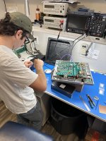
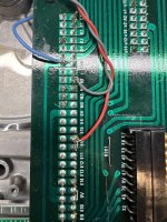
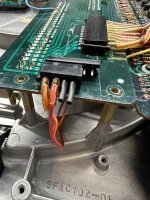
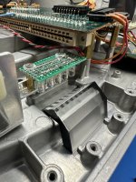
Matt was over a few days ago and we finished up the final bits on his Mk2, looked at the speeds, tweaked them a teeny bit, and converted from strobe to LED.
Attachments
Last edited:

The plastic nut goes down inside the base to lock the wire in the 2 cutouts. you may need to make a cap that screws down into the surround.The brass ground spike is M7 x 1.00, for those like me who are missing the original nut. Made one up from a 1/4" x 20 nut by drilling and tapping.
Next, I have a proper sized hole saw coming tomorrow, along with proper length M5 and M4 screws to mount the chassis to the plinth and the tonearm base to the arm board. Before that, I'll clean up the B500 base and get the black plastic parts looking better. Bearings appear to be in great shape.
Little by little...
Thanks, Warren. I didn't have an example to visualize, but couldn't understand why it is shaped with a point. I'll take a closer look and probably end up making one out of Delrin to do what you indicate it must. You're right - 7mm is not standard - glad I had the tap!
Long chassis bolts are on their way, here tomorrow, but thank you for the kind offer.
Long chassis bolts are on their way, here tomorrow, but thank you for the kind offer.


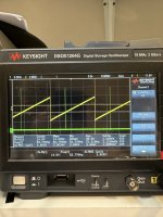
Very cool, Jim. Like the Keysight scope, too. Thanks for the photos - the LED board and 5V hookup pics were helpful. I'll plan on making one, as my neon is pretty dim now.
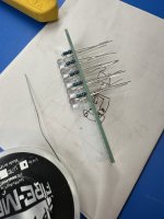
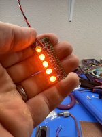
Although slightly off-topic, I made this large strobe LED for checking speeds (even though I also have a photo-tachometer). Opened up the polycarbonate cover, removed the filter cap from the circuit and glued in a PVC extension and power cord.
Oh, and obviously, this is used with a separate strobe disc...
Last edited:

Good progress made the last two days, despite finding lots of little extra jobs that need doing. The tonearm lock had a portion of the plastic missing around the threaded insert, so I repaired that by laying down several daubs of ABS glue, then re-shaping. The softer black plastic parts were a bit faded, so I used an automotive product to restore much of the black color, after cleaning off the oxidation.
Made up a Delrin ground nut, then decided to make one out of aluminum with an inside taper to take the brass point, then use it by feeding the ground wire into the end, per the diagram posted by JP. Works a treat.
I used a Denneson arm setup protractor to precisely locate the new mounting position of the tonearm in the arm board, then mounted the board to a wood milling fixture that I had made for another project, T-clamped to the milling table so that it would not move at all beneath the 60mm carbide hole saw while cutting. Perfect hole and alignment, with only a tiny bit of tearout on the bottom of the arm board that sanded right out. I then used a penetrating epoxy to saturate the end grain and plywood bottom surface of the arm board. New, nicer screws and washers now hold down the tonearm and board.
Noticing that the bottom enclosure of the turntable seems to resonate pretty easily, I added some automotive damping material to the outside of the enclosure. Not pretty, but it's inside the plinth, held down with new stainless screws.
Now this thing weighs a freakin' ton. It will be a two-person job to carry it out of my workroom through the house and place it onto the turntable shelf. Looks like it will need a wider shelf, also, but that was expected. In the meantime, I'll hook it up to my Neurochrome buffer so I can make a long cable run to the next room where the other stereo setup resides, and give it a test. I might make or buy some leveling feet, rather than shimming as I've done on the Micro Seiki.
Last edited:
The turntable is up and running, and sounding absolutely fantastic. Very flat frequency response, really fast transients, great bass and detail. I'm using the same cartridge off my Micro Seiki BL-91 for a fair comparison. It is quite impressive, particularly given that I've also got an Oracle Delphi which is no slouch. However, this is a completely different design/function paradigm, and I think one of the reasons, as Jim noted to me, that it works so well is the precise speed control.
Of course, heeding the many great suggestions from Jim, JP, Warrjon and others, seems to be paying great dividends. It's actually quite silly how good this sounds.
The tonearm is a lovely bit of engineering and functionality. The cartridge sits a bit close to the front of the plinth, only because the design of the arm board and plinth cutout/bracing made it impossible to move it further toward the rear without ruining the precise geometry. The plinth and chassis are really well damped (and the additional damping materials helps) - I tapped on the chassis and various parts of the plinth with very minimal thumping.
Even my wife has been noticing the differences, which is always encouraging!
- Home
- Source & Line
- Analogue Source
- The Incredible Technics SP-10 Thread