jam said:You ain't kidding! I would like to see the board layout for this. 😎
Jam
Think of a longer version somewhat similar to Upop Epop's (or however he spells his nic) amp.
The symmetrical front-end circuitry lends itself to a very straightforward and simple layout.
Cheers,
Glen
G.Kleinschmidt said:a longer version somewhat similar to Upop Epop's
Short for Upupa E-Poppers ?
Also with the entire electrolytic cap value that's required for a 2 1/4 amp bias level integrated on the board ?
Fast mover : http://www.diyaudio.com/forums/showthread.php?postid=1264624#post1264624
This guy is also thinking of steppin over to the THAT devices in his phoney works.
Wow!
Clearly the work of a madman...🙂
I used (yeah, I know -yawn) a pair of MJE15030/31 as the outputs in a speaker testing amp a while back but the damn thing oscillated itself into destruction.
Clearly the work of a madman...🙂
I used (yeah, I know -yawn) a pair of MJE15030/31 as the outputs in a speaker testing amp a while back but the damn thing oscillated itself into destruction.
Glen,
I guess Q23A and Q24A are symetrical buffers........very cool.
Now if you really want to impress us, how about a balanced bridge version? 😀
Kidding aside, it is a great looking design and there is a lot to be learned from it.
Regards,
Jam
I guess Q23A and Q24A are symetrical buffers........very cool.
Now if you really want to impress us, how about a balanced bridge version? 😀
Kidding aside, it is a great looking design and there is a lot to be learned from it.
Regards,
Jam
jacco vermeulen said:
Short for Upupa E-Poppers ?
Also with the entire electrolytic cap value that's required for a 2 1/4 amp bias level integrated on the board ?
No, only small local bypassing on the PCB.
Cheers, Glen
jam said:Now if you really want to impress us, how about a balanced bridge version? 😀
Problem with balanced bridge is that when you split the "single ended" output stage into two, you then have the load current handled by two pairs of half as many devices. That means double the current swing in each transistor

Cheers,
Glen
jam said:I would like to see the board layout for this. 😎
Slowly making progress......
I decided in the end to revert to my usual method of splitting the input/VAS and OPS onto seperate circuit boards.
The +45V and the -45V regulator boards for the input/VAS supply rails are underway now....
Cheers,
Glen
Attachments

G.Kleinschmidt said:
Problem with balanced bridge is that when you split the "single ended" output stage into two, you then have the load current handled by two pairs of half as many devices. That means double the current swing in each transistor
Cheers,
Glen
Glen,
I view balanced bridge as putting the output devices in series which provides better SOA for many devices than in parallel - depends of course on the supply voltage and output types.
Pete B.
PB2 said:
Glen,
I view balanced bridge as putting the output devices in series which provides better SOA for many devices than in parallel - depends of course on the supply voltage and output types.
Pete B.
Hi Pete.
Yes and No. The thing is with modern bipolar output devices, SOA freedom isn’t as much of as issue as it used to be, even when building moderately high power amplifiers.
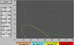
I’ll give you practical example of a 200W / 4ohm “single-ended” Vs bridged design with a load-line / SOA calculator I whacked up some time ago in MS basic.
Attached below is the load line for the single-ended situation. For an output power of 200W rms into 4 ohms the peak output voltage is 40V. The supply rail is set at 53V
The yellow trace is the output device dissipation through 180 degrees with the load current 45 degrees out of phase to simulate a realistic reactive load.
As can be seen, the transistor load line just fits inside the green trace, which is the SOA for 2 parallel pairs of MJL21193/MJL21194 transistors.
Attachments

And here is the bridged scenario.
For 200W rms into 4 ohms bridged we essentially need two anti-phase output stages rated at 100W into 2 ohms.
This is what is simulated in the attached screen shot. The peak output voltage is now 20V and the rail voltage is 28V.As can be seen, the load line is now enclosed by the SOA of just a single pair of output devices, but there isn’t any greater SOA freedom over the previous case.
Now consider a summary of the two options.
With 200W into 4 ohms the peak output/load voltage is 40V.
The peak load current is therefore 10A.
In the case of the single-ended amplifier with two pairs of output devices in parallel, each transistor passes a peak emitter current of only 5A.
In the case of the bridged amplifier with one pair of output devices per side, each transistor passes a peak emitter current of 10A.
The output stage of the bridged amplifier will therefore have significantly greater non-linearity due to the beta droop at high currents. This will be offset to some degree by the cancellation of even harmonics though.
The bridged version will also have significantly less reserve for delivering high peak load currents for brief bursts into less than nominal load impedances before the maximum Ic ratings are exceeded.
Cheers,
Glen
Attachments

Yes, nice work Glen. If you choose devices that remain on the constant power section of the SOA curve for your analysis then of course it will make no difference from an SOA perspective.
I agree about the beta droop and linearity, however more devices would probably be used once thermal derating is taken into account which would often double (or even 4X) the number of devices and bring the peak current back into the flat portion of the curve.
As I said it depends on the situation.
You design high power amps for low Z loads, this is another way to stay on the constant power section of the SOA curve, but if you were going for high power into 8 ohm loads with 80 to 100V supplies it would show the advantage with the series connection.
Also, your assuming a large drop across the output devices, 40V peak output and 53V supply? 13V difference? Are you assuming an unregulated supply, and power out under music conditions where the supply does not droop much?
At 20V out you used 28 V supply for an 8 V difference, why not one half of 13 to maintain the scale?
Anyway, an advantage from an SOA perspective is often seen with devices that show secondary breakdown at lower Vce's.
Pete B.
PB2 said:Yes, nice work Glen. If you choose devices that remain on the constant power section of the SOA curve for your analysis then of course it will make no difference from an SOA perspective.
I agree about the beta droop and linearity, however more devices would probably be used once thermal derating is taken into account which would often double (or even 4X) the number of devices and bring the peak current back into the flat portion of the curve.
As I said it depends on the situation.
You design high power amps for low Z loads, this is another way to stay on the constant power section of the SOA curve, but if you were going for high power into 8 ohm loads with 80 to 100V supplies it would show the advantage with the series connection.
Also, your assuming a large drop across the output devices, 40V peak output and 53V supply? 13V difference? Are you assuming an unregulated supply, and power out under music conditions where the supply does not droop much?
At 20V out you used 28 V supply for an 8 V difference, why not one half of 13 to maintain the scale?
Anyway, an advantage from an SOA perspective is often seen with devices that show secondary breakdown at lower Vce's.
Pete B.
Hi Pete.
This leads to another thing that is worth pointing out. Secondary breakdown limiting for the MJL's starts at about 75V.
Even so the sum of the rail voltages is 106V for the single-ended case, it can be seen from the first graph that I posted that above 75V Vce, there is very little current requirement.
The results aren't as bad as you'd think for a higher voltage situation either. Attached below is the single ended scenario for 200W into 8 ohms with +/-75V rails, again with two pairs of output devices.
With "balanced bridge" you loose out a bit on efficiency also because to have to provide an operating supply rail headroom for two power output stages. Generally, the bridged amplifiers total voltage rail headroom will be more than that of the single-ended situation, unless you want to build stiffer supplies by spending all that dough you saved on the cheaper lower-voltage electrolytic filter capacitors on even more uF and maybe even a bigger, better regulated transformer as well.
Cheers,
Glen
Attachments
The +/-45V regulator board......
An externally hosted image should be here but it was not working when we last tested it.
Attachments


Nice!!!
I'd try to get the red base drive trace under the emitter resistors so I could get a ground plane from upper to lower decoupling on the red side though... But maybe it won't be able to get through where all resistor connections are in a row? Could be solved by moving every other emitter resistor half a resistor length lengthwise 😀 It would look a bit strange though (but maybe cool?)
Or would that give too much capacitance from output node to ground?
megajocke said:Nice!!!
Thanks!
Here is the complete board; should give a better idea of what I was trying to do - earth return current flows back over the supply rail tracks.
The Vbe multiplier transistors will be mounted off board with short twisted wire leads. The output inductor and parallel resistor will be mounted off-board on stand-offs.
The on-board caps are only small local bypassing (4700uF per rail). Yeah, OTT, but why not? 🙂
Top layer:
An externally hosted image should be here but it was not working when we last tested it.
Bottom layer:
An externally hosted image should be here but it was not working when we last tested it.
Cheers,
Glen
Basic power supply and signal wiring.
Now all that is left to lay out is the the uC protection / relay timer DC detect / soft start board. I'm using a thermal circuit breaker for the mains in conjunction with a telema (sic?) current transformer feeding the ADC input of the PIC uC via an averaging detector........
Now all that is left to lay out is the the uC protection / relay timer DC detect / soft start board. I'm using a thermal circuit breaker for the mains in conjunction with a telema (sic?) current transformer feeding the ADC input of the PIC uC via an averaging detector........
Attachments

Bonsai said:**** hot SOA program Glen. Can you share it with us?
Sure.
Put these two files into the same folder and double click on the *.exe.
http://users.picknowl.com.au/~glenk/AMPCALC.EXE
http://users.picknowl.com.au/~glenk/VBRUN300.DLL
Cheers,
Glen
- Status
- Not open for further replies.
- Home
- Amplifiers
- Solid State
- The Kleinschmidt 25A