I agree. It did not seem okay to me as well; the amp caters for both by design.
If the SMSP is used, those are already optimised to deliver their rated current capability at a very broad frequency spectrum, i.e. they have very low output impedance at all required frequencies handled by an audio amp. As such, I do not see any reason to use capacitance multiplier PCBs. The SMPS should be wired directly to the amplifier PCB via very short and thick wiring, to preserve that low output impedance. Here, our mindset must let go of the linear power supply habits.
Furthermore (and this is what Patrick commented on when he said to use a separate power supply for each audio channel, to improve spatial presentation), if a single SMPS is used then... it is very important that the speaker return be wired directly to SMPS negative terminal. This will improve the spatial presentation even if a single power supply is used. This will isolate the large current speaker return draws right down to the SMPS PCB length between the negative terminal, and the common return on the SMPS PCB itself - very short. The signal return would then handle only... well... just the clean and stable ground reference and minuscule current, which will in turn make this amp sound really good even with a single power supply.
I really like what this amp could potentially offer and I'd like to see my suggestions implemented in real life by one of the brave builders. Even if disagree, just give it a go.
Yeah... but the SMPS, especially a good one, will have a very good noise figure.
The downside of having two points of common return and two sources of potential (the capacitors' banks, one inside the SMPS and the second located on the capmultiplier PCB - not to mention the additional wiring required....) to deliver the current to AMP, is the biggest disadvantage.
The downside of having two points of common return and two sources of potential (the capacitors' banks, one inside the SMPS and the second located on the capmultiplier PCB - not to mention the additional wiring required....) to deliver the current to AMP, is the biggest disadvantage.
A Meanwell RSP-500-24, which I consider a good industrial SMPS, has an output ripple of 150mVpp at 70kHz.
The opamp has about -40dB PSSR at 70kHz, the M2OPS even less, with its offset adjustment circuit.
Personally I am perfectly OK with speaker current returning to the Gnd point on the PCB.
Especially true if you are using 2x unipolar SMPS in series, and some sorm of regulators downstream.
The Gnd reference is given by the junction of the last two electrolytic capacitors on board.
This I would define as my star point.
https://sound-au.com/tcaas/jlhnewps.htm
But of course you are free to do what you think is right / better.
Cheers,
Patrick
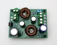
Inductors rated for >5 amperes are available at relatively low cost, with inductance values high enough to provide quite a bit of attenuation at SMPS frequencies (40 kHz - 5 MHz). Always remember that inductors have self capacitance, and capacitors have self inductance, so you're managing RLC resonances whether you like it or not. A little damping, applied skillfully, can mitigate this.
For a medium-low current application (3 amperes or less), I built such a filter, and it's in the diyAudio Store now. In that circuit, the Equivalent Series Resistance of the capacitor(s) was important, so I hunted for low ESR caps that would fit the existing PCB. Here is some of my early data .
Naturally you could build a cascade if you wished; LCLC to eliminate HF noise, followed by CapMul to eliminate 2 x Fmains noise. Yes, switch mode power supplies really do produce 100 Hz noise; Mean Well even includes scope photos of it in their Test Reports.
edit- adding a photo of an early prototype, higher current LCLC filter.
_
Attachments
Last edited:
Do you have schema and gerbers for the discrete preamp?Since Mark mentioned a discrete frontend in post #10, maybe it's good to show an example.
Not fully optimised yet, but in principle it works.
But one at a time.
View attachment 1095560
Patrick
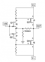
acamini tooRight hand PCB in #17 photo looks to be a voltage controlled current source a/k/a "transconductance amp" with anatomy that resembles this
_
So while most alpha testers prefer the opamp local feedback, it does have some drawbacks.
Namely a relatively high output impedance, from ~ 0.4R in Class A, rising to ~ 0.8R in Class B.
This means less control and more distortion when driven heavily.
A way round this is of coure to apply a controlled amount of global feedback instead.
This can be easily implemented in the current setup.
See attached description.
One alpha tester returned a positive feedback :
"Mixed feedback installed tonight. Scope shot below 10khz into reactive 8r load.
Exceptionally clean looking square wave (10V per division), so a sizeable enough output as well.
Initial impression is that the sound has shifted noticeably, and its has a more punchy sound, more impact (a good thing)."

And of course you can vary the amount of feedback to you taste, by changing only one resistor.")
Patrick
.
Namely a relatively high output impedance, from ~ 0.4R in Class A, rising to ~ 0.8R in Class B.
This means less control and more distortion when driven heavily.
A way round this is of coure to apply a controlled amount of global feedback instead.
This can be easily implemented in the current setup.
See attached description.
One alpha tester returned a positive feedback :
"Mixed feedback installed tonight. Scope shot below 10khz into reactive 8r load.
Exceptionally clean looking square wave (10V per division), so a sizeable enough output as well.
Initial impression is that the sound has shifted noticeably, and its has a more punchy sound, more impact (a good thing)."
And of course you can vary the amount of feedback to you taste, by changing only one resistor.
Patrick
.
Attachments
can be good for open baffle ....rising the Qts by QesSo while most alpha testers prefer the opamp local feedback, it does have some drawbacks.
Namely a relatively high output impedance, from ~ 0.4R in Class A, rising to ~ 0.8R in Class B.
This means less control and more distortion when driven heavily.
of course you can vary the amount of feedback to you taste, by changing only one resistor.
Patrick
.
Boards have arrived. I should have checked my mosfet stash sooner as I thought I had N/P matched pairs but it turns out that I have many quads of 9140 but no clearly matched N-P pairs - so some matching to be done before I start soldering and sorting out what configuration sounds best for me.

thanks for the opportunity to explore Patrick.
..dB
thanks for the opportunity to explore Patrick.
..dB
First time I see it in purple. Looks quite nice actually.
If the pads are gold plated, you might want to apply solder to all those pads you want to solder later on.
Then suck all that solder away to remove the dissolved gold, which when mixed with solder will cause embrittlement long term.
This is why we always use pre-tinned PCBs and not gold plated, not to save costs.
Unless you need the gold plate for dry contacts.
https://www.diyaudio.com/community/...reamp-with-output-buffers.384796/post-7064891
But then you need to plate hard gold, which very few shops will do.
And they will charge a fortune.
Patrick
I've listened more tonight, and to these ears, the mixed feedback is a good step up from local feedback (which I preferred to global). Setup was easy as per the PDF linked above and offset did not change - still at a few mV when warmed up fully.
The thing about the sound I noticed first was that it was more punchy, with vocals projected more, and a deeper soundstage. I really think its an improvement and it was no slouch before this.
As Patrick says, try it global, local and then mixed and see which you prefer. All you need to go from local to mixed is one resistor.
- Home
- Amplifiers
- Pass Labs
- The M2 Output Stage in Class A/B, and maybe a Power WHAMMY?