I believe an expanding array, like the one you are trying, could improve things. I had been simulating a version of the expanding array as well (6-3-2-1, with the 1 being a real tweeter), but it got put on the back burner for now. Would be interesting to find out how your experiment goes. Would you be able to change the middle group to a single element? Something tells me that five or six elements producing the highs is worse than 25 elements producing the highs, i.e., you want to transition to just one element above say 2 or 3 kHz.
Could something like this be the missing link?
")
I've often been asked why I build such a tall array. I've always replied with something like: If I didn't make it this tall, it just wouldn't work the same.
Seeing as we already have the drivers in Vituixcad it's easy to make a 5 driver array by simply dropping the other 20. Let's see what happens:

See how extremely small it makes the vertical beam width? When knowing it is a move from the center of the array to about 14 or 15 degrees off axis in the vertical plane when standing up, I can guarantee this will sound weird, in that standing position!
So, in other words, you need the tall array to steer the directivity. To get the pleasing outcome when moving up or down.
Frequency shaded vs non shaded array:

See how using this many drivers makes the bundle in the middle that much taller? Even with the unshaded array, you get similar tonality over a much wider vertical area. It doesn't flip on and off like a switch. It also makes sure we get that vertical directivity down to a much lower frequency.
So it isn't just done to be an impressive look with all those drivers in a row. It's just part of the concept. We do need them, not only to raise the output with ease, but also to cover that wide vertical area that sounds good. That's why I have arrays, the floor to ceiling kind. (actually about 70% of floor to ceiling height will be enough in most cases)
Seeing as we already have the drivers in Vituixcad it's easy to make a 5 driver array by simply dropping the other 20. Let's see what happens:
See how extremely small it makes the vertical beam width? When knowing it is a move from the center of the array to about 14 or 15 degrees off axis in the vertical plane when standing up, I can guarantee this will sound weird, in that standing position!
So, in other words, you need the tall array to steer the directivity. To get the pleasing outcome when moving up or down.
Frequency shaded vs non shaded array:
See how using this many drivers makes the bundle in the middle that much taller? Even with the unshaded array, you get similar tonality over a much wider vertical area. It doesn't flip on and off like a switch. It also makes sure we get that vertical directivity down to a much lower frequency.
So it isn't just done to be an impressive look with all those drivers in a row. It's just part of the concept. We do need them, not only to raise the output with ease, but also to cover that wide vertical area that sounds good. That's why I have arrays, the floor to ceiling kind
. (actually about 70% of floor to ceiling height will be enough in most cases)Attachments
Last edited:
Yes, precisely. I've already tried something similar, you know that. I tried it with a Fountek Neo CD3.5H, which has a small horn in front of the ribbon. I crossed it over at 3.0 kHz. There is a drastic reduction in the reflected HF energy in the room with the Fountek in place. The effect is quite dramatic. But it definitely pulls the location of instruments together a lot better than the bare arrays. The downside is headroom. The arrays just have so much clean volume capability.
The experiment with the Fountek led me to the 5-element tweeter (1") array, but that was a poor performer. My conclusion was that a single element (Fountek) is definitely preferable from a localization perspective, but even better would be a smooth handoff to that one element.
I made many sims in VituixCAD as well. My favorite was the 6-4-2-1 arrangement. Smoothest change in directivity. Maybe a short waveguide on the tweeter element ala speakerdave's Snell XA towers or the Revel Ultima Salon's would be the smoothest transition. Flank the waveguide with two closely spaced TC9s. Now if I only had the time
Been experimenting with a tube preamp and the F4. Heavenly sound. I used to think that there was very little to separate amps as long you operate them below clipping. Not that I built anything other than Nelson's Class A designs. But after hearing the F4, I changed my mind. It is so much more musical than all the other amps I've built. And the imaging--which seems silly to attribute to an amp--is so much better too.
Last edited:
wesayso's towers are probably among the very few loudspeaker systems capable recreating the largest spaces with the smallest footprint.
Hear hear! I can totally believe that. His attention to detail is unbelievable! One day I hope to get over there and have a listen.
Yes, precisely. I've already tried something similar, you know that. I tried it with a Fountek Neo CD3.5H, which has a small horn in front of the ribbon. I crossed it over at 3.0 kHz. There is a drastic reduction in the reflected HF energy in the room with the Fountek in place. The effect is quite dramatic. But it definitely pulls the location of instruments together a lot better than the bare arrays. The downside is headroom. The arrays just have so much clean volume capability.
That's the reason for me to be reluctant to make big changes all at once. Someday I may get there, but only if i can keep the dynamics.
The experiment with the Fountek led me to the 5-element tweeter (1") array, but that was a poor performer. My conclusion was that a single element (Fountek) is definitely preferable from a localization perspective, but even better would be a smooth handoff to that one element.
I made many sims in VituixCAD as well. My favorite was the 6-4-2-1 arrangement. Smoothest change in directivity. Maybe a short waveguide on the tweeter element ala speakerdave's Snell XA towers or the Revel Ultima Salon's would be the smoothest transition. Flank the waveguide with two closely spaced TC9s. Now if I only had the time
There should be an answer, and most probably a waveguide will be involved
. With the new tools available to us like Vituixcad and Mabat's horn tool we (as DIY crowd) have more power than ever before!Been experimenting with a tube preamp and the F4. Heavenly sound. I used to think that there was very little to separate amps as long you operate them below clipping. Not that I built anything other than Nelson's Class A designs. But after hearing the F4, I changed my mind. It is so much more musical than all the other amps I've built. And the imaging--which seems silly to attribute to an amp--is so much better too.
So glad to read that. I know there's a lot of doubt on this subject, but after hearing the possible differences first hand I cannot deny it any longer. There are differences in an amp/speaker synergy. Some combinations work better than others. I have to thank koldby and BYRTT for their visit that drove that point home for me.
Been experimenting with a tube preamp and the F4. Heavenly sound. I used to think that there was very little to separate amps as long you operate them below clipping. Not that I built anything other than Nelson's Class A designs. But after hearing the F4, I changed my mind. It is so much more musical than all the other amps I've built. And the imaging--which seems silly to attribute to an amp--is so much better too.
ra7,
Thanks for sharing this particular experience along your journey.
What crossover point would you choose and what would be the needed horizontal and vertical directivity at that point to create the smoothest transition to the rest of the line ?There should be an answer, and most probably a waveguide will be involved
Those are good questions, as can be seen in the sim by nc535, in his thread crossing steeply (linear phase) at 5 K or above keeps a small segment of the side lobes visible in the vertical plot. A less steep crossover should be lower plus we have the fact that it isn't the same array as I have simmed, as it is done with separate driver groups and FIR filters.
So no passive crossovers were used there. The other sim from him on that same page is a totally different setup. So we need to look into it a bit further.
Crumbo has done some legwork as well, most of these exercises so far used a planar tweeter (taller vertical than horizontal) which still need a bit of work. From Crumbo we should need more details (schematics and directivity patterns) to see what he has done.
Were you planning on using Mabat's tool to try and create a one-off waveguide? As a sim exercise it should be fun to see if we can work towards a solution. One thing this tweeter would have to be is plenty dynamic. Which is why I would want to run the array as high up as we can and have a sturdy tweeter do the top end.
Out in the real world I will have to learn/find out if going this route is the actual way forward. In other words: do my filters work to create a better, more smooth outcome than an unshaded array?
If it does work, I'd think crossing in the ~3.5 KHz neighborhood should work for a frequency shaded array (with a still to be determined steepness) if we can match the array in pattern control around that frequency. Which would mean realizing an even beam of +/- 15 degree vertical, dropping in SPL reasonably fast beyond that.

And about 50 degree at 3.5 KHz in horizontal direction (and this doesn't have to end as shallow on top as the single TC9 driver or array, but should at least be as wide at the higher frequencies as the array can manage. Preferably a smooth transition is the goal here.

Horizontal directivity of an array.
The fractal array is a good example of vertical controlled directivity, with a planar or ribbon tweeter on top, but I doubt it would be able to match the 25 driver array in dynamics. It is an awesome result though, on paper. Meaning I haven't seen or heard much of it since that thread.
BYRTT came close to the top end we'd need here: https://www.diyaudio.com/forums/multi-way/330031-fractal-array-straight-cbt-passive-xos-eq-4.html#post5606522
It looks like that specific top end of BButterfield's own experiment was done by using an Aurum Cantus AST2560 tweeter and possibly an array of small tweeters? (2 groups of drivers used in the sim for the top end) above the ~3.5 KHz.
Ideally we'd need one driver for the top end that has more than enough capacity to keep up with the arrays.
So no passive crossovers were used there. The other sim from him on that same page is a totally different setup. So we need to look into it a bit further.
Crumbo has done some legwork as well, most of these exercises so far used a planar tweeter (taller vertical than horizontal) which still need a bit of work. From Crumbo we should need more details (schematics and directivity patterns) to see what he has done.
Were you planning on using Mabat's tool to try and create a one-off waveguide? As a sim exercise it should be fun to see if we can work towards a solution. One thing this tweeter would have to be is plenty dynamic. Which is why I would want to run the array as high up as we can and have a sturdy tweeter do the top end.
Out in the real world I will have to learn/find out if going this route is the actual way forward. In other words: do my filters work to create a better, more smooth outcome than an unshaded array?
If it does work, I'd think crossing in the ~3.5 KHz neighborhood should work for a frequency shaded array (with a still to be determined steepness) if we can match the array in pattern control around that frequency. Which would mean realizing an even beam of +/- 15 degree vertical, dropping in SPL reasonably fast beyond that.
And about 50 degree at 3.5 KHz in horizontal direction (and this doesn't have to end as shallow on top as the single TC9 driver or array, but should at least be as wide at the higher frequencies as the array can manage. Preferably a smooth transition is the goal here.
Horizontal directivity of an array.
The fractal array is a good example of vertical controlled directivity, with a planar or ribbon tweeter on top, but I doubt it would be able to match the 25 driver array in dynamics. It is an awesome result though, on paper. Meaning I haven't seen or heard much of it since that thread.
BYRTT came close to the top end we'd need here: https://www.diyaudio.com/forums/multi-way/330031-fractal-array-straight-cbt-passive-xos-eq-4.html#post5606522
It looks like that specific top end of BButterfield's own experiment was done by using an Aurum Cantus AST2560 tweeter and possibly an array of small tweeters? (2 groups of drivers used in the sim for the top end) above the ~3.5 KHz.
Ideally we'd need one driver for the top end that has more than enough capacity to keep up with the arrays.
Attachments
Last edited:
From my own fractal sims you need to cross before the lobing starts or not far past it unless you are willing to go linear phase FIR. I have no interest in building a more than two way active array even as a simulation, a mixture of passive frequency shading and two way active is as far as I would go down that path.crossing steeply (linear phase) at 5 K or above keeps a small segment of the side lobes visible in the vertical plot. most of these exercises so far used a planar tweeter (taller vertical than horizontal) which still need a bit of work.
I am happy to give modelling a suitable driver / guide combination a go. I have a feeling an Ath waveguide won't be the answer, because of the astigmatism caused by the difference between V and H coverage angles but 15 V and 50 H might be OK. ABEC can be used to model different sizes of rectangular sources mated to small waveguide to match the directivities much like follgott did with his speaker.Were you planning on using Mabat's tool to try and create a one-off waveguide? As a sim exercise it should be fun to see if we can work towards a solution. One thing this tweeter would have to be is plenty dynamic. Which is why I would want to run the array as high up as we can and have a sturdy tweeter do the top end.
We will be doing this backwards looking for a tweeter to fit the lines directivity rather than matching the line to the tweeter.
That will be the litmus testOut in the real world I will have to learn/find out if going this route is the actual way forward. In other words: do my filters work to create a better, more smooth outcome than an unshaded array?
Can you post the polars from vituix array sims on a +90 to -90 scale and limit the frequency to the area of interest to get a better look at the needed directivity vs frequency? On the 360 deg plots the details are lost.
What I don't like about the fractal is the fingering seen from the large number of off axis lobes, that isn't something I want to trade forBYRTT came close to the top end we'd need here:
It looks like that specific top end of BButterfield's own experiment was done by using an Aurum Cantus AST2560 tweeter and possibly an array of small tweeters? (2 groups of drivers used in the sim for the top end) above the ~3.5 KHz.
This is the actual speaker where two of the smaller groups have been combined First build: Slim wall speakers. Some startup questions
I think the same or better could be achieved with a frequency shaded line of TC9's with the tweeter in the middle. The shallow cabinet depth for an on wall speaker limits the options for this specific design and is probably why it is not popular.
That's where it may be necessary to go two way active, most tweeters could get loud enough but there would be a power mismatch if the array is to be fullrange.Ideally we'd need one driver for the top end that has more than enough capacity to keep up with the arrays.
I'll see what I can do with polars, that shouldn't be hard.
I was of the same opinion to draw the line (no pun intended) at a two way active. I'm not even sure it is needed, as I have high hopes that a frequency shaded array will outperform these unshaded arrays. Making it one hell of a speaker!
The thing that worries me about a tweeter is the vertical shape, should we need a waveguide. If there's an option to find a tall ribbon/planar that fits our needs...
I do believe the frequency shaded array with the right tweeter should match or surpass the performance of the fractal array. It comes quite close to what Dunlavy was doing, only simpler and maybe even more effective due to being (almost) continuous throughout the frequency spectrum.
Last edited:
Do you want polar lines within the area of interest? Horizontal shouldn't be hard, but to get angles in vertical direction might not be easy.
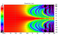
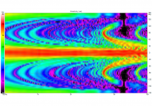
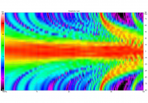
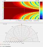
Here's a more detailed vertical plot:

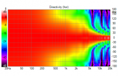
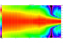
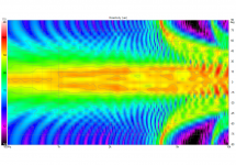
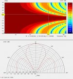
and horizontal:

Which does show these results rock! I.M.H.O.
Here's a more detailed vertical plot:
and horizontal:
Which does show these results rock! I.M.H.O.
Attachments
Go into the Options and Under Power and DI tick half space which will constrain the polar map to see it better, contours would be helpful to see the -6dB point.
The other chart that is easier to home in on is the polar chart, right click to select it instead of the polar map. Then use the scroll bar at the bottom to move to the frequencies of interest. That should make it clearer where the pattern is for the different frequencies.
The other chart that is easier to home in on is the polar chart, right click to select it instead of the polar map. Then use the scroll bar at the bottom to move to the frequencies of interest. That should make it clearer where the pattern is for the different frequencies.
I think a ribbon or the like will probably be the better option with a high crossover frequency, the size needed will depend on the pattern required. I imagine it might not have to be that long with a suitable waveguide to help tune it.The thing that worries me about a tweeter is the vertical shape, should we need a waveguide. If there's an option to find a tall ribbon/planar that fits our needs...
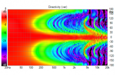
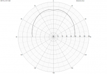
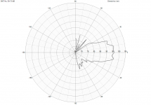
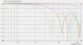
Aiming at the ~3.5 KHz, it would look like this... Charts not normalized
Attachments
-
 25x TC9 FR Shaded 19.0 as build Directivity (hor-chart).png174.7 KB · Views: 282
 -
 25x TC9 FR Shaded 19.0 as build Directivity (hor-polar).png260.7 KB · Views: 274
 -
 25x TC9 FR Shaded 19.0 as build Directivity (ver-chart).png176.5 KB · Views: 285
 -
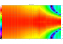
 25x TC9 FR Shaded 19.0 as build Directivity (ver-polar).png453.3 KB · Views: 279
Last edited:
If we were to go for that central tweeter, not saying we are...
Do take the above plots for what they are. Basically a different goal was at hand. I tried to optimize the listening axis and 10 cm up and down from there. I couldn't tell you at what angle those positions would be, as I just changed the room (within Vituixcad, mainly speaker position + floor and ceiling) to correspond with that height. Making plots in 2.5 cm increments over that 20 cm span. As an afterthought I optimized the standing height to not be weird or strange. In fact I believe it would be better than what an unshaded array would give. In hindsight I could have altered the split up of the groups to reach my goals even somewhat different, as I've re-arranged the 5x5 groups to better achieve those goals. But for mostly seated listening, Home Theatre etc, this is as far as I could (or was willing to) go, while retaining the balance at standing heights and moving about the house.
But if we'd add a central tweeter to the mix, that could mean redoing all that work while letting go of the top end improvements that I needed to keep, thus an entirely different set of goals. That would change the focus to another part of the spectrum, and probably make it easier to get good results.
I just wanted to get that out here, as one should realize/remember what the target was for the plots above.
The change that was made:
A-A
A-A
A-A
A-A
A-A
B-B
B-B
B-B
B-B
B-B
C-D
C-D
C-C
C-C
C-C --> design axis
D-C
D-C
D-D
D-D
D-D
E-E
E-E
E-E
E-E
E-E
Left is original grouping, 5x5 drivers, left is the re-arranged pattern to optimize seated positions. With a central tweeter, it would depend on the pattern control where to stick it in the line to get optimal behavior over a wide vertical area. What I could have done different is to drop one of the A drivers all the way to the bottom and move the rest up, so I'd have 3 drivers above the central listening axis (group of 5) and 2 below. That would potentially have a better result at standing positions wile retaining all other factors. It would also involve some weird wiring that I wanted to avoid. The basic change I did now was much easier to accomplish. It required way less surgery so to speak.
When adding a central tweeter, basically that tweeter will determine where it needs to go for best performance, the rest of the driver groups would follow.
Meaning: there would be a lot of freedom if one designed it this way from the get/go. For instance wire them in 6 groups of 4 drivers and you'd really have a lot of freedom to go wild. as you could wire the drivers in groups of two above and below the central position etc. Giving the user a lot of freedom in the filters used to shape the beam up to the frequency of interest.
Hope that makes sense.
Last edited:
I tried to optimize the listening axis and 10 cm up and down from there. I couldn't tell you at what angle those positions would be, as I just changed the room (within Vituixcad, mainly speaker position + floor and ceiling) to correspond with that height.
It is a 2.12 degree angle. I guess I can tell you
.If we were to go for that central tweeter, not saying we are...
But if we'd add a central tweeter to the mix, that could mean redoing all that work while letting go of the top end improvements that I needed to keep, thus an entirely different set of goals. That would change the focus to another part of the spectrum, and probably make it easier to get good results.
For instance wire them in 6 groups of 4 drivers and you'd really have a lot of freedom to go wild. as you could wire the drivers in groups of two above and below the central position etc. Giving the user a lot of freedom in the filters used to shape the beam up to the frequency of interest.
Hope that makes sense.
That all makes sense
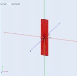
I've made a couple of simulations of ideal rectangular membranes in ABEC, a real driver will not be this well behaved but the important thing is that the directivity will be pretty close. I was too optimistic before about the length needed. It seems like it needs to somewhere around 120mm long to come close. The lower the crossover point the longer the driver needs to be vertically. This has a down side in that the off axis starts to develop more nulls and generally becomes less well behaved. This is kind of what is seen in Crumboo's simulations, the TPL150 gets extremely narrow and directive in the last two octaves.
Polar maps attached below
The horizontal is virtually 180 due to being on an infinite baffle, but could be constrained with a waveguide if this seems like something worth pursuing even if only virtually
Attachments
Last edited:
That doesn't come unexpected for me...
Basically, the top end disturbance results from many times the exact same driver spacing. We may be able to reduce the effect if we would vary the spacing in a straight array?
If we look at the nflawp paper by Mr. Griffin we'd need an even longer tweeter to keep us in the nearfield at ~3M listening distance, but that's another matter.
Maybe it would be interesting to see what we could do with an array as described (6x4 drivers, optimized for the part up to the wanted crossover) with a central tweeter like this in between.
Obviously, in a current 25 driver we'd hope to maybe remove one driver and stick a tweeter there. But that would mean the tweeter being about 85mm max vertically.
120 would mean to replace two positions. Thus, creating a bigger gap in the line, hoping we can still get a good outcome up to the crossover.
So we'd better do it as a virtual exercise first, trying to come up with an ideal setup.
After that it would be easier to see what we're willing to let go.
Last edited:
- Home
- Loudspeakers
- Full Range
- The making of: The Two Towers (a 25 driver Full Range line array)