Hi,
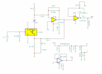
I'm designing a preamp for large diaphram capsule. I was wondering about the need of R0 in the circuit below. I'm afraid that R0 = 1GΩ will add thermal noise to this circuit. On the other hand there is extra capacity of microphone capsule. Will this circuit work properly if I omit R0 resistor?

I'm designing a preamp for large diaphram capsule. I was wondering about the need of R0 in the circuit below. I'm afraid that R0 = 1GΩ will add thermal noise to this circuit. On the other hand there is extra capacity of microphone capsule. Will this circuit work properly if I omit R0 resistor?
The greater the resistance, the less thermal noise current the resistor injects into the signal path. Hence the 1 to 10 Gohm resistors.
Without it, leakage currents will determine what voltage the gate will float to. Things like PCB leakage can then easily upset the bias point. In fact you already need a good, clean PCB with the 1 Gohm resistor.
Without it, leakage currents will determine what voltage the gate will float to. Things like PCB leakage can then easily upset the bias point. In fact you already need a good, clean PCB with the 1 Gohm resistor.
At this point I would like to try with chinese capsule that had good reviews but it doesn't have any datasheet. I started digging and some people call this electret microphone. If it is true, then I will have to buy other capsule...


No. I'm designing non distortion source. Assuming there is truly condeser capsule: why it can't be? You mean there is risk that circuit goes saturation without Rsource resistor? I'm thinking about adding it. The circuit would be more linear.
With the 2SK209 this simple circuit probably won't work.
You could make a test where R0 is a 1 or 10Mohm resistor, replace the capsule by a capacitor (e.g. 100nF) and feed a signal to that capacitor from a signal generator.
The current in the FET probably needs some stabilization, since at 0V gate-source voltage, the drain current seems to be somewhere between 1 and 14mA, depending on the device. If you have a possibility to do so, you should simulate the circuit first, keeping in mind that there is a large spread between devices.
If the capsule is an electret type, you don't need the 48V supply, so that will just simplify the design. I don't think you need to buy another capsule, just remove the 48V supply.
The capsule probably has a capacitance in the order of 75pF. That is why you need a very high value resistor for R0. Otherwise you will get a high pass filter at a rather high frequency. With 75pF and 1Gohm the high pass filter will be at 2Hz. If you use 1Mohm this will move to 2 kHz.
Once the DC bias is in place and you get a signal through, make sure that the whole thing is shielded well with a metal mesh network. Just a small leak can mean a lot of hum and other noise coupling into the connection from the capsule (wire soldered to the solder lug) to the gate of the FET.
And, as pointed out above, make sure that the PCB is clean! A guard ring around the gate can also be beneficial, depending on the PCB layout.
No. The N Jfet gate will get charged positive up until breakdown. That very node must be kept at zero volt with R0 whatsoever.Will this circuit work properly if I omit R0 resistor?
Thanks for all questions. It turned out that it is electret capsule. I decided to create other circuit. The funny thing is that old circuit (1st post) will not work. R2 should be connect to +2,5V.

Will it be overkill to use USB VBUS as power supply? Maybe I should use isolated DC-DC converter to avoid ground loop. I'm going to have two cables: USB and 3.5mm jack cable to line-in input. At this point I decided to create filter and don't use DC-DC isolator.make sure that the whole thing is shielded well with a metal mesh network.

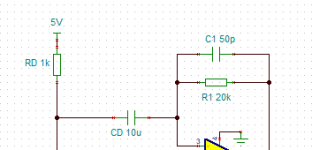
Did you run a simulated frequency sweep? The Rd, Cd, R1& C1 arrangement can create unwanted poles or zero's.to create other circuit
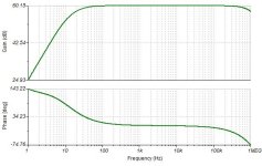
@Citizen124032 I've changed a bit R1. I ran simulations:


I also think about reducing CD to 1u. In simulations everything looks properly.


I also think about reducing CD to 1u. In simulations everything looks properly.
Last edited:
- Home
- Source & Line
- Analog Line Level
- The need of jFET gate resistor in condenser microphone preamp