Back to other diodes but only get 16.09V....
It is possible that the lowered reading is also due to oscillations - you moved the current source away from the supply capacitors. I think you need to find if you have that oscillaion problem, or not. Adding extra capacitance is one thing that might help.
Also, increasing the IRF9610 gate resistor from 220R to 1K may help, if you have no scope to debug it.
I increased cap to 1000uF but still bad, I will change now the 220R to 1K to see what happen, thanks for you kind support Rod.
Did the 1000uF make the voltage increase to 17.7V again?
Also, could try connecting a 0.01 to 0.47uF [any that you have] across the LEDs. Film capacitors, to bypass the electrolytic ....
Also, could try connecting a 0.01 to 0.47uF [any that you have] across the LEDs. Film capacitors, to bypass the electrolytic ....
Did the 1000uF make the voltage increase to 17.7V again?
Also, could try connecting a 0.01 to 0.47uF [any that you have] across the LEDs. Film capacitors, to bypass the electrolytic ....
Ooops I increased C1 in the CCS to 1000uF instead the 100uF, PSU cap is always 4700uF 35V, DCin 15.93V, have I to change C1 in the CCS for 100uF?
C1 in the CCS should be 100uF, that's OK.
AND you need 1000uF between DC+ and DC-, very close to the IRF9610.
AND you need 1000uF between DC+ and DC-, very close to the IRF9610.
Guys, sorry for intervening, wasn't online much today to follow you anyway, but looking at the progress, a question came to my mind. Since you are trying to separate the constant current source from the initial reg design example and to current feed a dummy load and eventually a heater, shouldn't there be a test with a stabilizing capacitance across its output with some ESR damping (i.e. an output lytic) and/or a slower Mosfet even?
Well, now changed C1 for 100uF, added 1000uF & connected the positive cap to G IRF9610 the negative connected to gnd, LED's lit🙂, DCin 15.86V, G-S 6.74V, voltage across R1 1.84V, voltage across dummy load 1.98V
Last edited:
Guys, sorry for intervening, wasn't online much today to follow you anyway, but looking at the progress, a question came to my mind. Since you are trying to separate the constant current source from the initial reg design example and to current feed a dummy load and eventually a heater, shouldn't there be a test with a stabilizing capacitance across its output with some ESR damping (i.e. an output lytic) and/or a slower Mosfet even?
Yes, I agree, connecting 47uF or 100uF across the dummy load is worth trying.
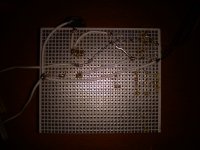
Please check the connexion of the 1000uF. It should be from the DC supply [+ pin] positive to ground [- pin]. mounted on short wires, and located near the IRF9610
You are right, there should be no lumped inductance in the input or output loop of a fast Mosfet CCS. The input cap ought to decouple very near. I would also say that the 47-100uF test across the load maybe better be on perf board near the 9610 than on the load itself.
Yes, I agree, connecting 47uF or 100uF across the dummy load is worth trying.
Please check the connexion of the 1000uF. It should be from the DC supply [+ pin] positive to ground [- pin]. mounted on short wires, and located near the IRF9610
It's correct?
Attachments
You are right, there should be no lumped inductance in the input or output loop of a fast Mosfet CCS. The input cap ought to decouple very near. I would also say that the 47-100uF test across the load maybe better be on perf board near the 9610 than on the load itself.
I have to added 1 cap at the input & other one at the output CCS both 47-100uF?
Hi Iko, please don't use Mr. for me thanks, I'm trying this one
With these changes:
DCin 16V
R1 15R
R2 1K
R3 2K
Dummy load 16R 25W
1000uF connected the positive to G IRF9610 negative to gnd
With these changes:
DCin 16V
R1 15R
R2 1K
R3 2K
Dummy load 16R 25W
1000uF connected the positive to G IRF9610 negative to gnd

Is the 16R load connected from the point that says 6.1V to ground?
What voltage do you have across R3, and what voltage do you have in total across all LEDs?
What voltage do you have across R3, and what voltage do you have in total across all LEDs?
Yes it's connected the dummy load, voltage across R3 is oscillating between 7.43 & 7.49V, voltage across 5 Leds als oscillating between 8.66 & 8.70V
Last edited:

Did I get the circuit right? This is how it simulates.
Also, if I may ask, what are you planning to power with this?
C1 wrong place it's after the LEDs & before is R10 47R, forgot 1000uF between R1 & source IRF9610
For 6922 filament

- Status
- Not open for further replies.
- Home
- Amplifiers
- Power Supplies
- The simplistic Salas low voltage shunt regulator