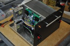
I finally finished the SIT NFET NFET MUFF Mutant Power Amplifier. The initial ideas for this design were discussed in the thread https://www.diyaudio.com/community/threads/pimping-papas-sit-muffs.392149/post-7172622.
The output stage is based on the last schematic in the Nelson Pass paper “BAF 2022 SIT Power Amplifiers” https://www.diyaudio.com/community/attachments/baf-2022-sit-amplifiers-pdf.1101782/, shown in the first image below.
The front end gain stage is based of the "New Stasis Front End" described in https://www.diyaudio.com/community/threads/new-stasis-front-end.363701/, but has been simplified. My PCB for the front end has more "features" than shown in the simplified schematic below, which I will explain later posts.
AS BUILT SPECIFICATIONS:
Inputs: single-ended RCA or XLR balanced
Input impedance: 10k
Gain: 20dB
Distortion @1 watt: 0.12% (without feedback)
Damping Factor: 90 (without feedback)
Output power 8 ohms: 50W
Output power 4 ohms: 30W
Output Noise level: 100uV or below.
Power consumption: 330 watts
Output Stage Power:
75V power supply
70V rail voltage (5V lost due to capacitor multiplier noise filter)
2A bias current per channel
Front End Power:
2 x 36V switching mode power supplies (SMPS)
Attachments
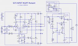

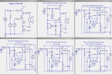
Output Stage Circuit Evolution:
The output stage is based on the last schematic in the Nelson Pass paper “BAF 2022 SIT Power Amplifiers” https://www.diyaudio.com/community/attachments/baf-2022-sit-amplifiers-pdf.1101782/, shown in the 1st circuit below. The circuit numberings are in left to right, top to bottom order.
1 2 3
4 5 6
Using the optocoupler circuit for the PFET MUFF we get the 2nd circuit. Notice that the opto LED, the phototransistor and the bias filter capacitor are all referenced to ground, and the voltages are only a few volts, with the LED and its resistor requiring about 1.2V. This is a situation where an optocoupler is unnecessary and in fact limits choices for circuit parameters.
The 3rd circuit shows a bias circuit based on a voltage comparator. It is a differential amplifier whose inputs are the transistor emitters with the base voltages being held equal. The circuit has the appearance of a current mirror but it functions to compare the voltage at Out- to the reference voltage across the pot P1. The reference voltage can be quite low, allowing for lower bias currents and lower values for R1 and R2.
In the 4th circuit resistor R1 is eliminated, causing a potential problem if Out- is accidently shorted to ground, which would cause excessive current through the output FETs, if lucky only blowing the power supply fuse, but possibly blowing the IXYS NFET.
THE HYBRID:
The 5th circuit shows the Nmuff mutant topology where the ground reference is moved to Out-. This not only work properly but also has slightly higher damping factor than before. My Nmuff output stage is based on this topology with resistor R1 removed, as shown in the 6th circuit.
Attachments
Last edited:
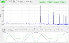
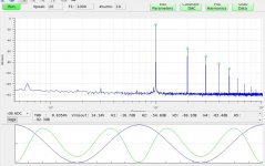
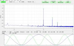
Performance Measurements:
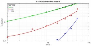
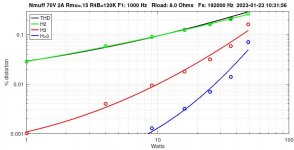
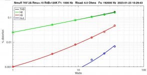
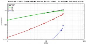
The first three images show harmonic spectra at 1W, 25W, and 50W for 1kHz sine and an 8 Ohm load.
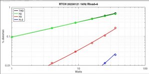
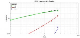
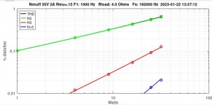
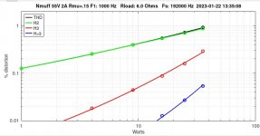
The final three images show harmonic distortion sweeps for 8 ohm, 6 ohm, and 4 ohm loads. Note that the relative levels of H2 and H3 do not depend on speaker load impedance.
The first three images show harmonic spectra at 1W, 25W, and 50W for 1kHz sine and an 8 Ohm load.
The final three images show harmonic distortion sweeps for 8 ohm, 6 ohm, and 4 ohm loads. Note that the relative levels of H2 and H3 do not depend on speaker load impedance.
Attachments
-
 Nmuff-RTCH-20230121-50W-1kHz-8R-spectrum-1.jpg99.6 KB · Views: 163
 -
 Nmuff-RTCH-20230121-25W-1kHz-8R-spectrum-1.jpg100 KB · Views: 173
 -
 Nmuff-RTCH-20230121-1W-1kHz-8R-spectrum-1.jpg100.2 KB · Views: 161
 -
 Nmuff-RTCH-20230121-8R-watt-sweep-1.jpg71.4 KB · Views: 153
 -
 Nmuff-RTCH-20230121-6R-watt-sweep-1.jpg68.7 KB · Views: 119
 -
 Nmuff-RTCH-20230121-4R-watt-sweep-1.jpg66.9 KB · Views: 162
Global Negative Feedback:
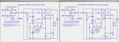
I designed the front-end PCB to allow for negative feedback from the outpujt stage.
The 1st circuit shows a front end gain stage based on an opamp with negative feedback from both FEOut and Out+ through resistors R3 and R4.
The resistor values R1, R2, R3, and R4 accomplish the following:
. R2/R1 is the FE voltage gain.
. R3 and R4 are chosen such that R3 || R4/Aos = R2 and the desired level of negative from Out- is achieved. The 2nd image show the resistor values for 12dB negative feedback in my build.
Details of my Stasis based front end gain stage will be described in more detail later.
Attachments
Performance Measurements With 12db Negative Feedback:
With 12dB feedback from output stage:
Damping factor: 180
Distortion @1 watt: 0.03%
These images show harmonic distortion sweeps for 8 ohm, 6 ohm, and 4 ohm loads. As expected, all harmonics are reduced by about 12dB.
With 12dB feedback from output stage:
Damping factor: 180
Distortion @1 watt: 0.03%
These images show harmonic distortion sweeps for 8 ohm, 6 ohm, and 4 ohm loads. As expected, all harmonics are reduced by about 12dB.
Attachments
Reducing The Overall Power Consumption:
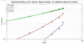
Here is one more set of measurements. Using a Variac to lower the AC mains voltage for 55V to the output stage, I get the following performance:
With no feedback from output stage:
60 power supply
55V rail voltage (5V lost due to capacitor multiplier noise filter)
2A bias current per channel
Power consumption: 270W
Distortion @1 watt 8 : 0.13%
Output power: 32W @8R, 36W @6R, 32W @4R
This configuration provides the most uniform performance across all load impedances.
Attachments
I need clear head to follow your musings and, then, sometimes even that isn't sufficient
I mean, I understand schematics, but your'e loosing me at math
when I was younger I was good with math, but later found plenty more ways to not being good with, so jumped in that direction

............ all to say - good work, as always!
I mean, I understand schematics, but your'e loosing me at math
when I was younger I was good with math, but later found plenty more ways to not being good with, so jumped in that direction
............ all to say - good work, as always!
What math? The only math was for the feedback resistor values, which I will eventually explain in more detail.I need clear head to follow your musings and, then, sometimes even that isn't sufficient
I mean, I understand schematics, but your'e loosing me at math
when I was younger I was good with math, but later found plenty more ways to not being good with, so jumped in that direction
............ all to say - good work, as always!
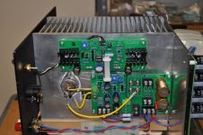
The output stage is powered by a simple linear supply using an Antek AN-6458 transformer. Each channel has it own secondary, bridge rectifier, and CRC filter.Very Nicely done. What SMPS are you using?
The front end uses pair of Mean Well LRS-35-36 36V 36W SMPS supplies. These are overkill, but the lower wattage chassis mount supplies from Mean Well and TDK-Lambda were not available.
I am still evaluating, but with no feedback I was suspecting listening fatigue from the high second harmonic level even at 1 Watt. 12dB feedback might be more than needed.Any impressions listening without feedback and with feedback ?
just too much for me .......
don't take me so serious ....... even if you must agree that this one is with least math, of all your endeavors
was speaking in general
Maybe the thread title should have been "NFET MUFFs for Dummies". .

Awesome! Any chance you'd post the gerbers?
Also, question . . . In the Zen 3, Papa layers in "Modulating the Regulated Supply". Would one gain a similar benefit here with less dissipation and more swing even though it's only a cm? Would it give some partial benefits of a cascode to the sit like in lu amps?
Also, question . . . In the Zen 3, Papa layers in "Modulating the Regulated Supply". Would one gain a similar benefit here with less dissipation and more swing even though it's only a cm? Would it give some partial benefits of a cascode to the sit like in lu amps?
zchopper:
Free the Gerbers! Maybe.
I am not sure what you suggest about the Zen 3 "Modulated Regulated Supply". My output stage uses a simple capacitor multiplier which looks similar, but does not attempt to regulate to a particular voltage. Its only purpose is to remove ripple noise from main power supply. It does a good job at that, reducing the noise from around 70mV rms to about 0.2mV rms.
I have never had to opportunity to listen to a SET amplifier, but that might be expected from a SET. My guess is that the FET mu follower is preserving (following) the harmonic character produced by the SIT which is mainly 2nd harmonic.Hi Lynn,
This looks great! So the benefits of this output topology is a nice second harmonic signature that remains consistent with varying loads? Would you say it's dynamically adjusting the load line to obtain this?
Thanks,
During listening, the lack of 3rd harmonic is noticable, particularly where it is expected from transients like from guitar plucks or percussive piano key strikes.
Perhaps Papa can comment on this issue.
Not too sure either. I was thinking how lu1014 was originally tamed and now every single place it shows up, it has extra low distortion without feedback. I've been reading Papa's cascode paper, and thinkin maybe it's not just the Lu, but the cascode. The Tokin has such capacitance and at low voltages it doesn't appear really linear to me . . . One might be able to "modulate" the CM in your circuit similar the the zenv3. Or further, like maybe this.zchopper:
Free the Gerbers! Maybe.
I am not sure what you suggest about the Zen 3 "Modulated Regulated Supply". My output stage uses a simple capacitor multiplier which looks similar, but does not attempt to regulate to a particular voltage. Its only purpose is to remove ripple noise from main power supply. It does a good job at that, reducing the noise from around 70mV rms to about 0.2mV rms.
It does kinda ruin the spectra, and starts clipping a few watts earlier, but I just threw in some guesses for resistor values.
- Home
- Amplifiers
- Pass Labs
- The SIT NFET MUFF Mutant Power Amplifier