Are you sure the problem is in the mid driver?So is there no easy way to attenuate a bit of the brightness of the upper mid range? Maybe replace the 5.6uF cap with with a diferent value cap?
If not trained explicitly for this kind of things, nobody is able to understand what is the exact range of frequencies where the problem lies and type of problem the speaker has. Something it is also very difficult to pin down the driver affected. And a professional music player is no exception, and I say it being a viola player with a degree in music (and one in physics). This is where measurement equipment is essential.
Another point: do you ever listened to the speakers with the factory crossover but new components? (original values, new components) Or are you sure that the drivers don't have faults (e.g. partially dried ferrofluid, in need of reconing, ...)
Ralf
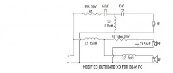
Thanks for the suggestion. And just to clarify, the 6.8uF is in the tweeter filter. The mid has a 5.6uF.Increase the 6.8µF across the mid to the next available value, i.e. 8.2µF (or 7.5µF if you have one). Small changes can be made by paralleling a small value, e.g. 6.8µF + 0.47µF ≈ 7.3µF. Any two values just add together when paralleled.
My mistake, I meant the one across the midrange, i.e.5.6. Increasing it's value will reduce output at the upper end of the midrange. Try a 6.8 in place of the 5.6, and see if that's going in the right direction, then fine tune if it is.Thanks for the suggestion. And just to clarify, the 6.8uF is in the tweeter filter. The mid has a 5.6uF.
Sort of wrong, it's complex. If the drivers were a simple R it would work, but they are not, their equivalent electrical circuit is complicated. At a very simplistic level the drivers have self inductance in their voice coils, which causes the impedance to rise with frequency, so the attenuation effect of a series resistor reduces as frequency goes up. From your description that's not what how you want to tweak the midrange.
This is in my post# 97. "So the sound is pretty good but the upper end of the mid rage is a little bright/accenutated. Can I fix that with a resistor in the mid range filter?" So your remark, "so the attenuation effect of a series resistor reduces as frequency goes up", makes me think a resistor is a good place to start. Would you agree?Sort of wrong, it's complex. If the drivers were a simple R it would work, but they are not, their equivalent electrical circuit is complicated. At a very simplistic level the drivers have self inductance in their voice coils, which causes the impedance to rise with frequency, so the attenuation effect of a series resistor reduces as frequency goes up. From your description that's not what how you want to tweak the midrange.
There might be an issue with the meaning of words because musicians and sound engineers often have slightly different meanings for the same words. When you say "the upper end of the mid rage is a little bright/accenutated" in the context of a crossover design discussion my tendency is to think you mean the output of the midrange driver, where as a typical musical doesn't think about the system components, just the overall system response.
So when a musician says it sounds "bright at the upper end of the midrange" they are likely talking about the overall sound, not any particular component; and the "midrange" is used as a subjective term, not an object one referring to a specific driver or crossover section. It sometimes takes a bit of to-ing and fro-ing to get on the same page. I've worked with musical types a lot, including supplying sound systems for the Conservatorium of Music at Adelaide University and the director and I took a while to understand each other.
So when a musician says it sounds "bright at the upper end of the midrange" they are likely talking about the overall sound, not any particular component; and the "midrange" is used as a subjective term, not an object one referring to a specific driver or crossover section. It sometimes takes a bit of to-ing and fro-ing to get on the same page. I've worked with musical types a lot, including supplying sound systems for the Conservatorium of Music at Adelaide University and the director and I took a while to understand each other.
Got it. I did read it incorrectly.No, please reread my post carefully. As the resistor will have the least effect at the upper end of the midrange driver where you actually want it to have the most effect.
Just for information, below is a simplified electrical equivalent circuit for what the crosover "sees" connected to the output of each section, i.e. the driver. Any change to the crossover circuitry is interacting with this imaginary equivalent circuitry inside the driver, which isn't drawn on the schematic. In the circuit below, the crossover electrical output from one section is represented by the '𝖾↑' symbol on the left hand side, and on the right hand side '𝗿𝖠' represents acoustic output of the driver. There are three drivers in your system and each has a similar equivalent circuit. The total acoustic output of the system is notionally the sum of the three 𝗿𝖠's, but still must take into account the physical positions of the drivers relative to each other and the shape and size of the baffle.

The B&W site seems to have no specifics for the drivers in the P6. Your diagram identifies the tweeter as DT 94 4ohms and the mid and woofer as WS 17 E 8ohms. What do the lables relate to? Do you know the specs. for the P6 drivers?What a confusing thread! All is muddled! Here's what I have learned. Because I know B&W quite well.
I'm not convinced R1 at the tweeter input is 5.6R at all. It might be 0.56R! Written R56. It is seven watts for sure. 20W would be for a bass circuit. Measure it!
Tweeter is ferrofluid in the P6 and apparently has a tendency to dry out. Killing the top end. The fluid reacted with the surround glue and went solid sometimes. If that is the issue, I would clean it out altogether, but you could try replacing.
Usual internet advice to update the ageing NP capacitors. A last resort I would think, they usually work for me. But cheap entertainment.
Tweeter polarity seems to be much in doubt. It's usually positive in 6" speakers. It's actually quite hard to hear the difference in practise IMO.
Well, I looked up the P5 circuit which is all we have really. And did some simming. I doubt if it matters much the precise bass coil arrangements.
But the interesting thing is that adding a 4.7uF shunt capacitor and 1.8R resistor to the bassmid is a well known tweak on B&W 6" Kevlar speakers. Reduces cone breakup around 5kHz. People usually take the tweeter level down too. Because B&W can be a bit showroom bright.
http://rutcho.com/tweaks/01_bw_dm601s3/bw_dm601s3.html
So I’ve tried resistors in series from 3R to 9R and none tame the overly bright/loud upper piano notes. My attachment shows the addition of what I thought would be an L pad. Does this make any sense? Or are there other ways to attenuate the problem tones?The B&W site seems to have no specifics for the drivers in the P6. Your diagram identifies the tweeter as DT 94 4ohms and the mid and woofer as WS 17 E 8ohms. What do the lables relate to? Do you know the specs. for the P6 drivers?
No, clearly 2.5.Well, those are 3 way! And not in the 85 dB league! When I say 'put it in the picture', I really meant :show the speaker!
The distance between wf and mid...see the value of the inductor (subwoofer league)
- Home
- Loudspeakers
- Multi-Way
- Three way crossover question