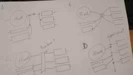
Hi, to the right of the 10mH inductor in the attached image, there appears to be a 6 way node. I'm hoping someone can recommend the best way of connecting all those components, as I'm definitely a novice. It's a lot of wires to solder together. I've drawn up a few options I can think of. The first question I guess would be, are those options all actually equivalent?
Option A doesn't require more than 2 wires to be connected at any point, but might create a bottle-neck in the thin wire on the left of the top capacitor. I don't know if that is significant given the very short length, but ultimately a lot of power feeds two woofers thru that little wire. (I guess a similar question applies to the 3 leads out of the 3 caps to the 2 woofers, which is a 5 way node).
In option B, I would maybe use solder tags (eye terminals) on each lead all connected to a bolt, or perhaps a butt splice connector with 3 leads crimped and soldered into each end of the connector.
Option C would use a brass busbar with screw connectors,
Option D is merely a variation of C, using a copper wire with all the leads soldered to various points. I guess there are other variations of this option, like using a screw terminal strip or a solder tagstrip with a copper wire bridging the terminals/tags.
I see that a lot of people use crimp and screw connectors in crossovers, and others solders wires directly to each other or to tagstrips. Is there anything inherently wrong with any of these methods?
I hope this all makes sense and I haven't used too much wrong terminology. As I said, I'm definitely a novice and I've spent a fair bit of money on parts so I don't want to stuff it up.
Attachments

Al your methods would work, but there's no need to overthink this.
Solder up the parallel blocks then join the blocks together via their mid-points as in Fig. B. The join can simply be a soldered length of reasonable gauge wire.
Remember that a short length of component or connecting wire has negligible resistance, so no 'bottle-necks' would result.
P.S. I prefer soldering rather than crimp and screw connectors - more reliable and permanent.
Last edited:
First decide how the parts will be mounted - often people glue the large coils & caps to a small piece of plywood: You don't want heavy components dangling.
Then connecting them is easy as Galu says.
See DIY-Loudspeakers
for pictures of crossover construction.
Then connecting them is easy as Galu says.
See DIY-Loudspeakers
for pictures of crossover construction.
Star connections are not my fave. I never connect more than two wires together at one point.
Last edited:
I don't regard either of the methods to be inherently wrong in the sense that they could affect the electrical operation of the crossover.Is there anything inherently wrong with any of these methods?
My preference is for a directly soldered method of construction rather than one depending on tags and bolts.
If we take into account rayma's preference, then option D with a bus bar of solid copper wire looks absolutely fine to me.
"My preference is for a directly soldered method of construction rather than one depending on tags and bolts."
Definitely, particularly in a speaker.
Definitely, particularly in a speaker.
Thanks to everyone for the advice. I do have a slight tendency to overthink things, but seeing things done many different ways makes me wonder if there really is a significant difference, and if so, why. I will definitely go with soldered connections. I should have noticed before that the 10mH inductor, a Mundorf BS100 (1mm diameter wire), has 4.5cm of bare wire at each end, so presumably I could solder the caps and resistor to points along that wire, rather than using another piece of wire as a bus bar.
Just purely out of interest - what is the reason for not using more than 2 lugs on a single bolt?
Just purely out of interest - what is the reason for not using more than 2 lugs on a single bolt?
- Home
- Design & Build
- Construction Tips
- tips for connecting multiple wires in xover