will it work?
So if I cut according to faustian's diagram, but turning the piece 11.25 degrees (how do you make the degree symbol?), then it should work with perfect integrity.
Steve, I think I was resigned to making compound cuts a while ago, so your warnings have been heeded.
Or ignored, whichever.
Naysayers are an important aspect in any project. If it doesn't work, then you can say, "I was right." If it does work, then I still have to say, "Not without some insight from Steve concerning the difficulties."
Unless someone has something to add, I'm going to give it a go according to Faustian's scheme sometime today or this evening. I'll post photos of the early work.
Dave
Kneadle:
I presume if you cut pieces according to Faustian's formula, you will end up with his result. I am in no position to actually check the work without making the model.
I realize now that I had the angles wrong. I figured that as long as I pointed the Line upward, it would keep on going upward like a straight line. I now realize that if I had done that, all that would have happened would be that the Line could curl back upon itself. So we needed software to properly calculate that angle, and Faustian provided it. I have no way to check his figures, however.
Are you cutting the pieces by hand? I had a hunch that was part of the idea of limiting the numbers of pieces. I figured your idea was-get the proper equipment if borrowable or affordable, if not, 28 pieces cut by hand is not out of the question.
One thing. Have you considered making a dry run? I was thinking that many caprpet places have their long cardboard centers available for the taking-I've gone there and had the salesman simply direct me to the back of the store. You might want to try a quick prototype. Paper is eady to cut. At least when you go cutting the PVC, you will have a little more conficence that cutting things this way will actually yield the results you were envisioning.
Do you have an idea how to rotate the PVC exactly 11 degrees? Incidentally, I don't think you can put the "degree symbol" on this board, or any board. I do have a way, if you want the description. Haven't tried it, it is just an idea.
I'll come clean--yes, I'm doing it with a hacksaw, by hand. The blade is 12", and I've found, by experimenting, that I won't have tooooo much trouble. It'll take some energy and time, but hey, how did they build spiral shaped enclosures back before electricity?
I was going to build a prototype out of cardboard, and the furniture store idea is a great heads-up.
In addition to practicing on it, I can also make "jigs" out of it to guide my saw when I'm making significant cuts. Or at least something to look at so I don't just get wildly out of proportion.
For the 11.25 degree angle, I'm going to use Sch3mat1c's idea for that by using a little board and some lines which are drawn using a regular polygon, something akin to what Faustian was talking about.
Anything else I should be aware of?
Dave
Dave.. I found it easier to cut pvc with a plain old crosscut hand saw than with a hacksaw.. The courser teeth let go of the chips easier.. during cutting.. even by hand.. the blade can get hot enough that the chips want to clog up the saw. (actually this might no be a problem with scheadul 40 ... I was using much heavier pipe..) If you decide to do this by hand you will want to first make a jig to hold the pipe and guide your blade. Basically just a trough to lay the pipe in...if you make the walls tall enough you can use them as a guide to make your cut. I still would consider using a compound miter saw.. hand sawing leaves a rough edge which may be difficult to glue.. even if you achieve a perfect cut. Dewalt makes a 12 inch compound miter saw which would make short work of this project.... it is kinda pricy.. but I'm sure you could rent one if you had to.
another thought.. you could make a simple prototype just using 2X2 lumbar.. just use the 2X2 instead of the pipe.. use the same measurements and angles.. you can assemble it with glue and wood screws.. just make certain that all the surfaces line up... it will be alot easier than prototyping with pipe.
good luck..
a little insight into the modelmaking process. i built it basically exactly the same way the pieces would be assembled in reality: piece by piece. i didn't use any formulae for laying out the spiral; i just stuck each piece together and rotated. you'll just have to trust me that the dimensions i noted are correct. 
so yes, if you build it according to my scheme, it will look pretty much like the drawings. i didn't do any 'fudging'.
and i'm pretty sure the overall form will look very similar if you use the rotated cut method as well. i hope that method works for you because it will look better at the joints.
---
now, as for the base connection piece...that's a bit more complicated. as you noted, the bottom piece is neither parallel nor perpendicular with the ground, which would have made things easier. i'll have a go at determining an angle to cut the last 'wedge' that will allow for mounting a true vertical base piece. the trick is to get the center of gravity more-or-less over the base, for stability. you will still need to attach the base piece to a heavy base, because otherwise the whole spiral will be prone to toppling once you mount the driver.
ttyl
/andrew - trying to look like he's working
*** EDIT ***
by the way, just to clarify for those keeping score at home, 45 degrees is one-eighth of a circle; 22.5 degrees is one-sixteenth; and 11.25 degrees is one-thirtysecond. for a template, one can graphically mark each division by successive bisecting. i just had a thought...i'll be posting something in a minute.
faustian bargin said:---
now, as for the base connection piece...that's a bit more complicated. as you noted, the bottom piece is neither parallel nor perpendicular with the ground, which would have made things easier. i'll have a go at determining an angle to cut the last 'wedge' that will allow for mounting a true vertical base piece. the trick is to get the center of gravity more-or-less over the base, for stability. you will still need to attach the base piece to a heavy base, because otherwise the whole spiral will be prone to toppling once you mount the driver.
Actually, I think the original idea was just to have the last piece lie flat on the ground, with the 7.25" length horizontally along the ground. I think it was understood that other mounts would have to be made, so "center-of-gravity" considerations aren't there. Still, if there is a way to put the base piece at the "center-of-gravity", maybe that is the way to go.
Mostly, I just want to make sure that the last piece is fully horizontal, not vertical, since a vertical piece will face down toward the floor, closing off the Transmission Line completely.
kelticwizard said:the base piece at the "center-of-gravity"
You could consider running a pole up the middle and suspend it from that.
dave
planet10 said:
You could consider running a pole up the middle and suspend it from that.
Can I do nothing that will be a surprise? Won't it just be gorgeous? This was in the original plans as well!
Look at my avatar.
Dave
I'm sure your modeling process is accurate.. have you looked at it to scale... relative to the thickness of the pipe? If you take a piece of 2 inch scheadual 40 pvc and join two sections cut at 22.25 degrees.. you can twist them 11 degrees and still make contact on all edges.. though that contact will be skimpy at some points. What if you take a 6 inch sceadual pipe and do the same thing? The thickness of the pipe does not increase proportionately with the increasing diameter.. I suspect that the pipe will not make contact at all points..
Aparently this issue is resolved by making each cut with the pipe rotated by 11 degrees. Which brings up another problem.. how to line up the pipe for the cut in the first place .. here is a easy solution.. the first cut for each piece is of no particular consequence.. cut it any orientation that you like.. the next cut needs to be oriented at 11 degrees to the first... place a cut piece of pipe in your jig rotated 191 degrees to your intended cut.. then just line your work piece up against the end of the first piece and make your next cut.. but then... I could be wrong..
good luck
i think it would look cool to suspend it from a center pole. or maybe just have a few vertical pieces supporting the bottom full turn of the spiral. anyway to have the spiral 'floating' midair, i think that's a good visual effect to go for IMO. (see below)
i think i was unaware of the requirement to have the bottom piece open ended...that's why i proposed turning it down. (i never made a speaker before, so i don't know much about TL's.)
i think i was unaware of the requirement to have the bottom piece open ended...that's why i proposed turning it down. (i never made a speaker before, so i don't know much about TL's.)
Attachments
i took a closer look at the joints using 'my' scheme. if doing the rotated cut doesn't work out for you, i think my scheme's joints will be okay, if a little rough-looking.
at the smallest overlap, they still seem to have about 1/4" coverage. i.e. about 1/16" projecting on each side. i think that's enough to offer structural integrity, although i can't say what it does for the sound. probably negligible effect.
/andrew
at the smallest overlap, they still seem to have about 1/4" coverage. i.e. about 1/16" projecting on each side. i think that's enough to offer structural integrity, although i can't say what it does for the sound. probably negligible effect.
/andrew
faustian bargin said:i think it would look cool to suspend it from a center pole. or maybe just have a few vertical pieces supporting the bottom full turn of the spiral. anyway to have the spiral 'floating' midair, i think that's a good visual effect to go for IMO. (see below)
Think: clear PVC pipe!
Man, that is a GREAT diagram. What software are you using?
Dave
One last thing. You introduced the basic dimensions in post 75, which is here: http://www.diyaudio.com/forums/showthread.php?postid=124117#post124117 .
Are they still valid? If so, what are the dimensions of the end segment? If the long part is 7.5", what would the short part be? 3"?
Thanks,
Dave
Are they still valid? If so, what are the dimensions of the end segment? If the long part is 7.5", what would the short part be? 3"?
Thanks,
Dave
if i'm not mistaken, FOR THE END PIECE ONLY i think the long side is 7.5" and the short side is 4.5". a 3" difference...so if you need to add length, keep that in mind.
all the dimensions should still be valid, even for the rotated cut. (because the key dimension is 4.5" down the center of the wedge piece...that doesn't change no matter how much you rotate the pieces.)
/andrew
all the dimensions should still be valid, even for the rotated cut. (because the key dimension is 4.5" down the center of the wedge piece...that doesn't change no matter how much you rotate the pieces.)
/andrew
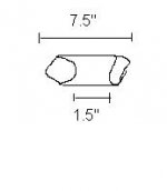
Here's how I plan to do it: measure and cut the end segment at 7.5" to the 4.5" mark for the 22.5 degree angle.
The second and succeeding segments follow thus: I measure 7.5" along the longest point, the 1.5" along the shortest part. Then, instead of cutting there, I'll turn the pipe 11.25 degrees and "slide" the marks over, which effectively changes the actual outside lengths, but, as I understand it, retains the 4.5" inside length.
Therefore, 2-dimensionally, the segments will each still be 7.5" and 1.5" long, respectively. The difference is the 3-dimensional orientation. See pic.
Any objections?
Dave
Attachments
- Status
- This old topic is closed. If you want to reopen this topic, contact a moderator using the "Report Post" button.
- Home
- Loudspeakers
- Multi-Way
- TL Design I can't build