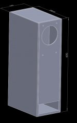
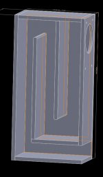
I am hoping to put two W5-2143's in TL boxes. My design is very simple (I am not very keen on the intensely theoretical aspects of TL design, shoot me now), and I have drawn it up in Solidworks, with some simple variables that drive the design so that it can be modified for different sizes of drivers and line lengths. Basically, the calculations take the Sd of the driver and a user selected taper factor and use them to size a three fold design. The baffles are straight, but each successive fold is a bit smaller. (I have an earlier version with angled baffles). The cross section of the line is then driven by the Sd and the desired width of the box, and tapers from an area equal to the Sd times the taper factor (I usually use 1.5) down to an area equal to the Sd at the port. Then the design contains a sensor that measures the line length, and I adjust the height of the box manually to get the line length I want, which I usually match to 1/4 wave length of the Fs of the driver.
See screenshots 1 and 2 attached, I am interested in what anyone thinks about this approach to TL design, is it too simple, or might I be lucky on occasion and get a great sounding design out of this?
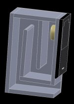
I currently have a system running at home with boxes made from my earlier angled baffle design (see screenshot 3) with FaitalPro 3FE22 drivers driven by a NAD 3020 amp and playing CDs on an old but nice Tascam deck, I really like the honest sound from these, and some surprising bass from a 3inch driver.
See screenshots 1 and 2 attached, I am interested in what anyone thinks about this approach to TL design, is it too simple, or might I be lucky on occasion and get a great sounding design out of this?
I currently have a system running at home with boxes made from my earlier angled baffle design (see screenshot 3) with FaitalPro 3FE22 drivers driven by a NAD 3020 amp and playing CDs on an old but nice Tascam deck, I really like the honest sound from these, and some surprising bass from a 3inch driver.
Attachments
I haven't time to do a proper check at this minute (give me an hour or so). However, I suspect you'll end up with a relatively low tuned line without a great deal of gain (output) due to the restricted cross section. The CSA of a TL has no connection to driver Sd and in general, designs that use Sd as a basis for the line CSA end up having too small a volume to produce decent output, especially if you tune to Fs. Line resonant frequency is also a function of axial length and taper, not just axial length.
You might get lucky on occasion designing like this -the thing is, those occasions usually tend to be rare; and more likely with drivers that have a very low Vas for a given Q, Fs.
You might get lucky on occasion designing like this -the thing is, those occasions usually tend to be rare; and more likely with drivers that have a very low Vas for a given Q, Fs.
Last edited:
Have you tried using the Leonard calculator to check out the response of the speaker. Pretty easy to use and free to download, you can then play with taper, filling and line length to get the best compromise. Often the speaker is not at the end of the line but a bit down the first part of the line to reduced the upper mid fluctuation that is often seen (check out picture of the internals of the PMC OB1). Again this is easy to sim using Leonard.
Others have also used Hornresp for this.
leonardaudio.co.uk
Others have also used Hornresp for this.
leonardaudio.co.uk
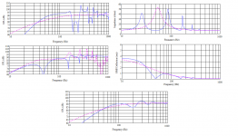
The attached is roughly what you'd get from the given line length, taper & CSA. Plots are undamped, apart from the lower, which is assuming lagged walls.
If you want a suggestion for a starting point (please do not take this as a finished design) you could try this: 35in line axial length, with 12:1 taper. Driver offset 11.75in from the sealed end. St = 564cm^2 (87.42in^2). That will put you tuned to ~Fs, & with the top, back & one sidewall lagged, will be more or less maximally flat under anechoic conditions.
If you want a suggestion for a starting point (please do not take this as a finished design) you could try this: 35in line axial length, with 12:1 taper. Driver offset 11.75in from the sealed end. St = 564cm^2 (87.42in^2). That will put you tuned to ~Fs, & with the top, back & one sidewall lagged, will be more or less maximally flat under anechoic conditions.
Attachments
Last edited:
Thanks, Ugg10, leonard audio seems to be defunct but I found that calculator elsewhere, and I'll give it a try. Anyone else have any thoughts on this design?
Link please, mine worked fine until recently when it popped up with an invalid 'parameter' and any attempt to figure it out just locks up the computer.

Hopefully I can retrieve/use all my data bases.
TIA,
GM
Here's a link to a thread where someone has a zip of the leonard audio program for download:
https://www.diyaudio.com/forums/software-tools/220421-transmission-line-modelling-software-81.html#post5160274
https://www.diyaudio.com/forums/software-tools/220421-transmission-line-modelling-software-81.html#post5160274
Hi there, your approach in designing transmission lines is closer to guess work than anything - first of all there are 2 ways of doing it - the theoretical way (based on known things such as formulas, rules of thumb etc), 99.99% of the time this is how you design an enclosure, the other way would be by practical method, by building several enclosures (or an adjustable enclosure) to see what happens, your method is not based on either.
TL are designed based on desired frequency response (and size concerns of the owner, and sometimes impulse response) based on the main TS parameters - Qts, Fs and Vas; I don't have the formulas immediately available to see which one influences what but here the simple version: the smaller the Qts (under 0.4 values) the less you get from your larger than bass reflex enclosure choice; Vas gives you the internal volume (larger Vas = larger enclosure, not Sd!); Fs and Qts will give desired tuning frequency / steepness of response bellow tuning. Ideal Qts for TL in therm of output is 0.5-0.6.
Other important observations: a constant cross section TL will have a simple formula to determine tuning frecv. but if the geometry is expanding or contracting the same formula is no longer valid; a contracting geometry will have a shorter line length for same tuning (don't think 0.5%, it may be 30%). Very important - TL are tolerant with variation in internal volume, a 10% variation sounds about the same, there is room for error. Another thing you have to know and understand about TL is the driver offset technique, when you place the driver at a position lower on the line, maximum is 33% from the closed end of the line; this will smooth out the response by controlling the other resonant frequencies (harmonics) of the pipe; the key spots are 20% offset and 33% offset, but you get similar results in between. Look at the graphs attached by Scottmoose - they don't look smooth, do they? because the driver is a the end of the line. In practice you might want to back off a little with internal volume to compensate for room gain etc etc.
As far as W5 2143 is concerned it's a driver that has low Qts (might wan't to measure it, it's not that simple in this case, measures done by others don't confirm Qts from published specs) and is not going to be particularly bassy but might need unexpectedly low internal volume - check this enclosure design from Bjohanessen - https://www.diyaudio.com/forums/full-range/88787-tabaq-tl-tang-band-223.html#post5606346 (https://www.diyaudio.com/forums/att...1542654890-tabaq-tl-tang-band-w5-2143-sim-pdf)
The published data suggests the Qt on the W5-2143 isn't all that low at 0.38, so assuming TB haven't given it more motor power than advertised that's not too much of an issue. Whether the spec. lines up is another matter -YMMV on that front! That said, assuming the factory data as the baseline then I agree, the Fs, Qt, Vas ratio means it doesn't require an especially large box if a tapered line is desired -see the quick & dirty dimensions I provided in my above post. 35in axial length, 12:1 taper, 33.6% driver offset (33% is not a practical maximum, sometimes significantly more is necessary depending on the specific design), St = 87.42in^2. Should give (more or less) a max-flat, Fp = [advertised] Fs line.
Last edited:
Thanks for all the help. I clearly will have to learn a lot to benefit from most of it, it is mostly going over my head. I took my rules of thumb from here: HiFi Loudspeaker Design. Is this info now outdated?[comment] first of all there are 2 ways of doing it - the theoretical way (based on known things such as formulas, rules of thumb etc), 99.99% of the time this is how you design an enclosure, the other way would be by practical method, by building several enclosures (or an adjustable enclosure) to see what happens,[/comment]
Are there newer rules of thumb that are relatively simple that I can go with? What's the best place to start to design a basic TL, or is there a different quarter wave concept that's easier to design? I am keen on getting the clear, honest sound that I heard during a brief stint working for PMC.
The short answer is - yes! it's outdated (the info in the link) but you do find your up to date info in one of the links on the page - Quarter Wavelength Loudspeaker Design - Martin J. King's website and probably the best information when it comes to transmission line enclosures. But bear in mind that there is (generally)not much on the subject, this is not exactly the most popular enclosure ever, so you might want to take a look at what closed pipes are in term of resonating systems... it's been used by people for tens of thousand of years and it's studied by physics and by people who make musical instruments. The chapter for enclosures using pipes it's a very short one and just recently added (1999) but it answers the question "how big?" for what parameters of the driver.
I can guide you in terms of sizes for w5 2143 (I own a pair and have sniffed the internet for all sorts of projects) but my main information source is Hornresp, I use it as a guide for internal volume and tuning freq. the rest is down to compromises.
As far as rules of thumb is concerned ... well driver size is related to enclosure size eventually, in the sense that a 3 incher will not have similar enclosure size needs compared to 5 incher, but two drivers of the same size might swap enclosures and be ok... if the drivers are designed for similar application (car audio has different suspensions for example). Other rules I know of - 3 inchers are very close in parameters, it's very easy to keep same the TL for many of them, TABAQ enclosure is a classic example for this. Interestingly people have been using the TABAQ enclosure with 4 inchers too, so TL are flexible (TABAQ is tuned very low and that is one of the reasons why it works). From memory I can tell you that I know before I put data in Hornresp that a 3 inch unit will be about 10 liters, a 4 inch about 20 (or lower), and a 5 incher above 20 liters. Another simple thing that saves you from designing things with simulations is to use the TABAQ architecture and make the port adjustable and you will heard different lengths and the one that sounds right you keep. A general rule for how big the terminus of the pipe should be - at least 50% of Sd to avoid too high speeds for moving air in and out of the terminus.
The "honest" sound you heard was due to low pressure inside the TL (compared to bassreflex/closed boxes), the theory is that a driver works like in an open baffle for frequencies that are not in the vicinity of the pipe resonances. You might want to try and keep walls from being to close to the driver - this is one of the advantages with TABAQ stile enclosure compared to traditional pipe, the cross section is larger so the walls are not that close.
Well, the short version is that the information on the site you link to was never actually in date.
Having had a quick read, I'm reminded of a comment from Top Gear a few years back: 'Some say he only knows two facts about ducks, and both of them are wrong.' It's not only that the methodology listed isn't up to much, it's also historically speaking inaccurate. For example, the original Acoustical Labyrinth was actually set to 1/2 wavelength of a given frequency, not 25% as different objectives were in play at the time (1936 -'37). I'm not recommending that by the way, just pointing out a factual error in the text. And so on and so forth. The 'proven by performance' statement is true enough -but unfortunately not quite in the way that is intended. The methodology stated certainly is proven by performance: the trouble is, most of the time, it's poor performance.
Like any other vented enclosure, pipe volume requirements in a TL / QW box are dominated by the driver's Qt, Vas. 99 times out of 100, a TL using a pipe CSA related to a small multiple of Sd will result in insufficient pipe volume & limited gain (output) for a given tuning. Which is before you get to twaddle like the 'damping material in order of preference' which provides absolutely zero factual reasoning behind the statements made. As it happens, of the four materials that are listed, the one stated as lowest in the order of preference is usually the most efficient of the bunch for a given density, and that's not a matter of opinion, it's measurable fact. What is also a fact of course is that the other three materials are also perfectly acceptable. first of all there are 2 ways of doing it - the theoretical way (based on known things such as formulas, rules of thumb etc), 99.99% of the time this is how you design an enclosure, the other way would be by practical method, by building several enclosures (or an adjustable enclosure) to see what happens,
Yep, you can certainly do the latter. Nothing wrong with cut & shut. However, unless you happen to enjoy the process of building multiple prototypes, the simpler and usually more effective solution is to design the speaker in advance, which most of the time will get you very close to your goals, and then fine tune from there.
Are there newer rules of thumb that are relatively simple that I can go with? What's the best place to start to design a basic TL, or is there a different quarter wave concept that's easier to design? I am keen on getting the clear, honest sound that I heard during a brief stint working for PMC.
Quarter Wavelength Loudspeaker Design
Go to the 'Transmission Line Theory' section; you will find a pdf of alignment tables, and if you don't want to break out the caclulator, there is also an excel file based on those that you can enter basic data into. This is one alignment of many possible, and provides decent, consistent results. It assumes you're tuning to Fs and gives a relatively well damped alignment with a modest amount of gain and quite well controlled harmonics.
Last edited:
Here's a link
Thanks, totally forgot about this modified one since mine was working fine at the time.
GM
I must be going boss-eyed -is there a post number for the zip file? Granted, it probably doesn't help that I've set my forum options to show 20 posts per page and that seems to foul up internal links.  I've still got the software installed, but I'm going to have to format my system HDD at some point soon & reinstall Win10 as it's gradually slowing (not done badly for a couple of years) so would lose it at that point, which would be a shame.
I've still got the software installed, but I'm going to have to format my system HDD at some point soon & reinstall Win10 as it's gradually slowing (not done badly for a couple of years) so would lose it at that point, which would be a shame.I must be going boss-eyed -is there a post number for the zip file? Granted, it probably doesn't help that I've set my forum options to show 20 posts per page and that seems to foul up internal links.
It's in post #803
https://www.diyaudio.com/forums/software-tools/220421-transmission-line-modelling-software-81.html#post5160274
What is your go-to? I am messing around with this and with Boxsim, and I can't make head or tail of it. I have give the Tang Band project to a friend, and I am now going to make a new set of boxes for my FaitalPro 3FE22s, since I have found out from you and krakatoa how wrong my designs were! I need them to to be as small as possible, so I am interested in doing a tapered TL, and I would like to fold it, but I can't make head or tail of how to begin simulating this in the leonard software. As I have time I'll try to post my results so you can see what I mean, but do you have any pointers to start off with for the 3FE22s?
I wouldn't necessarily scrap what you have at the moment. Methodologically speaking, what is on the site you linked to isn't great -however, given the low Vas and modest Q of the 3FE22, it probably won't be catastrophically bad; I suspect you'll have reasonable gain to Fp, with the main issue being a null at F3 due to the small driver offset, which is probably not excessive given the configuration. As noted, it's not a design method I'd recommend in a broad sense, but in this case, you've probably got results that are reasonable enough to make a rebuild a bit excessive. You can likely do 'better' but whether that would be 'better enough' to justify it is a different matter, given that you have them, and they're making music in a decent enough fashion from what you've said. My advice: leave them alone & when the time comes for the next project, focus on that one.
- Status
- This old topic is closed. If you want to reopen this topic, contact a moderator using the "Report Post" button.
- Home
- Loudspeakers
- Full Range
- TL design with Tangband W-5-2143