Finished the toroid mount, but the tubing walks up the acrylic. I think I will switch to the 3/8th tubing. I suspect I will have to use compressed air to get it on the posts.
Tomorrow I have to build a box to hold the winder, and I will get back to the rings.
Pics on Monday.
Jn
Tomorrow I have to build a box to hold the winder, and I will get back to the rings.
Pics on Monday.
Jn
Picked up a 5 mil (.005 inch) razor saw blade to cut the rings. Micro mart if I remember correctly. Did one cut, works really nice. Had real problems cutting the .018 thick stainless,, so backed into brass. Using it for the hinge material for opening the rings to go through the toroid. Pics tomorrow.
Btw, if anyone would like the info on where I bought anything, just ask... I am learning here...making mistakes, and having fun. Any reason to buy a tool...is a good one..
Ps.. Going direct drive put the motor under the rest, so the box is done. Pics of course. Once the rings are done, I will mount the arduino and PWM stepper boards.
Jn
Last edited:
Pics of the toroid drive mounted.
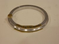
Next pic is the drive ring. I had a real problem with the steel shim I wanted to use, so substituted brass shim. I hope it is strong enough.
The left piecs, the small hole will be used for locking the ring closed. On the right brass, the far right screw will be used as the hinge point. I will back the two screws a tad, and loctite them using the purple stuff.
The backside brass, well I realized why use two pieces...duh.
Note just under the left hand pin is where I cut the ring using the razor saw. The five mil kerf is awesome. Once I finish the backside brass, I will cut the ring between the right two screws to finish the hinge.
Last pic is the box I made to hold the winder. Melamine board, apparently I had an old shelf 😕 . On the box is the arduino, two PWM drive boards for the motors, and a display board.
jn
Attachments


Looking v. interesting... One ring to wind them all!
Actually, two rings. I only now was brave enough to tackle how to hinge the rings, starting with the easiest one. The second one requires I drill several holes .060 dia hole in a ring side where the width is .104 and the depth is .250. I have been learning how to use my milling machine to do that, it has digital read outs good to .0002 inches.
If anyone is interested, I could take pics of the setups as I figure out how to do this. I always love it when the machinists at work show me how they do their thing, their talents amaze me. I learn so much from them, and would like to pass it on if others express an interest.
Jn
..If anyone is interested, I could take pics of the setups as I figure out how to do this..
Yes please!
Here are videos of three types I know of.
First is a two ring version of the type I am making.. The left ring is the driven ring, and has a pulley to pay the wire off to the toroid. The right is the ring that holds all the wire.
YouTube
Second is a single ring belt style. As the wire comes off the ring, paddles in the center hold it steady until the ring rotates so that where the wire leaves the ring passes through the toroid. If you look really close, you can see that much of the time the wire is looped and not tight. the belt basically holds the wire from falling off the ring as the tension of the wire at the toroid goes to zero. As a result, the winds on the toroid are not perfect. The count is there, but I'm looking for better control of the lay of the wire.
YouTube
Third is a slider version. A sliding thing is attached to the single ring, and pays the wire off. Again, there are paddles to hold the wire as it goes loose.
The slider versions are supported on the inner radius of the ring, the slider attaches to the ring and controls payout. I can't find a good video of one.
jn
This is some seriously fine work you have going! 
Bet you'll be swamped with requests and purchase orders before you even get it finished.
Congrats,
Rick
Bet you'll be swamped with requests and purchase orders before you even get it finished.
Congrats,
Rick

Here is the tapping block I use to tap the 1-72 threads. The hole is .058 inches dia.
The hole in the block is the tap diameter to hold the tap upright. The bottom feet were milled to be perfectly flat.
So far, I've not wiped any threads nor broken any tap.. All threads were into aluminum.
Oh, and I don't use the handle, all I do is turn the knurled part between thumb and forefinger.
jn
Attachments


So far, I've not wiped any threads nor broken any tap.. All threads were into aluminum.
Oh, and I don't use the handle, all I do is turn the knurled part between thumb and forefinger.
tapping is just like barbecue, low and slow.
Cheers
Alan
Here is the 5 mil wide kerf razor saw I used. These puppies are very delicate. First two cuts went well on the drive ring, then um....difficulties with the spooling ring. Overall, great saws, nice thin kerf, but plan on buying them ten at a time. I broke three. Seriously thinking of making an electric saw using a dc motor with a reciprocating action..
Second is both rings cut with brass sides installed. The left driven ring, I was able to hinge. The right, spool ring, the pivot point was too close to the inner edge, I was not able to hinge it outward so made it fully removable.
This is one of those mistakes....note to self, hinge it inward next time.
Third is a shot of both rings in place. Next I have to lathe the three v groove pulleys holding the spool ring. I have to provide clearance for the little part that will extend over the spool wall to gather up the wire and direct it to the wire feed pulley. I do not want to scrape the wire over the spool ring wall.
Next chip cutting time will be next week..road trip to a vendor now..
jn
Attachments


Second is both rings cut with brass sides installed.
Where are these spools originated from?
Main was made on a lathe from large and thick steel industrial pipe and it was a hell work.
My spools are three inches outside diameter, 76 mm.Where are these spools originated from?
Main was made on a lathe from large and thick steel industrial pipe and it was a hell work.
The screws are #1-72.
Just came back from a vendor visit, to see if we want to buy a used toroid winder. Interesting...not sure.
Meantime, purchased some materials to make unit number two, incorporating some things I learned..
Jn
Edit: I finally figured out how to get pictures at home. It involved an Imac, an SD, and a USB...
First pic, all the design choices which did not pan out. Recall the saying, the first casualty of war is the battle plan...well, hardware and design share that exactly... Those are the parts that for various reasons, refused to play well with me.. the wire hook I was unable to use to gather the wire off the ring..for scale, the hook wire is .037 inch diameter, the holes in the brass are countersunk for #1-72 screws and .020 inch thick. The spring wire is .013 inch diameter.
Second pic is the completed drive ring. I went with a thicker brass side piece for the hinge, and replaced that silly wire thingy with a silver tube. I inserted a barely clear steel wire into the tube so I could bend it without closing the bore. Worked quite well. Note I used silver for the clarity it provides with sound..
Third pic shows how the silver tube goes over the ring wall. It is tangential to the ring so the wire doesn't hit top or bottom of the gather tube.
Fourth shows the wire already loaded, passed through the tube, and over the pully down towards the work. That is a #32 awg wire.
Fifth is the brake for wire tension control, it is a brass sliding weight. By lifting the rod high enough, the weight slides down the rod and engages the bracket, holding the brake up off the ring.
Sixth is the overall mechanism setup to load the ring with wire. I built a mount for the source spool on the right, a brass gathering post to guide the wire towards the brass slotted rod, that is used to align the wire to the reel for loading. Note the brake is lifted in that pic as well. That wire is #28 awg.
Last is the control board, an Arduino with two pwm stepper driver boards capable of 8 microstep. 700 ma, and running 12 volts for now. Note that the electronics is mounted on a 1/4 inch thick acrylic board. I decided not to use a sheet of thick aluminum, much cheaper with the plastic. When it's done, I will remove the backing paper.
Ah, another note. I used VHB transfer tape to hold the belt in the drive ring. I learned very quickly that the surface of the belt has to be well abraded or the tape doesn't hold, it just gets dirty.
jn
Attachments


Last edited:
First pic, #32AWG magnet wire wound on the toroid using the spacing of a #28AWG wire. Wire is 8.5 mil, spacing 13.5. This was a first test of the Arduino control with the itty bitty drive modules.
Second pic is the #32AWG wound using the 8.5 mil spacing on the inner radius. I use a spreadsheet to calc the ratio between ring and toroid for the wire size.
Note that there are a few gaps in the wind. When I ran that wind, I was seeing how fast I could run the machine... At around 4 to 5 turns per second, the ring motor stalls. Since it is an open loop system, it is not aware of a stall so the toroid continues to turn.
In the code, I ratio the two motors. The ratio depends on the gauge of the wire and the toroid ID. The ring rotates once every 616 steps (the ring driver is set to no microsteps so 200 pulses per motor rotation.) The toroid motor is set to 8 microsteps, and the physical drive setup is about 2:1.
Eventually I might modify the wind algorithms to freeze the toroid rotation as the wire is being planted on ID and OD, with rotation only occurring on top and bottom. Not sure if that will help much on multilayer winds. Definitely having fun.
The Arduino code is designed to calculate the time between pulses and wait that time. If the speed is set to a 1k pulse rate, the code waits 1000 microseconds. 2K rate is 500 usec.
It's not the most elegant way to do it, but it is totally simple. I think when I include the serial communication to the LCD, it will slow the pulse rate a bit. I need the LCD, as I need to do a 500 turn coil, and there is no way I'm gonna count.. I can't get past 20 (shoes off).
I do note I had problems with digital input 13, I suspect the built in LED give the INPUT_PULLUP pinmode problems.. I also have some kind of problem with the drives at turn on. No movement, but can hear the motors...I have to see what the PWM frequency is. Also, I use a ten turn pot for velocity input, and the first 90 degrees of rotation are ugly. Might have to buy a USB 4 channel scope module to troubleshoot..
I tried to upload a video of winding, but the file size was too large. Anybody know how to do that?
John
Attachments


Last edited:
hope this works
The vid quality is not that good, it was off my phone and I guess it doesn't translate well.
Eventually I'll setup a tripod and take some good video that also doesn't make one seasick to watch.
I modified the core mechanism because the #28 awg was too big to pass by the rollers easily, it would stall. So I designed and built a chain drive to turn all three rollers. Now it works well.
I also have one roller spring loaded to hold the core in place and it accommodates the core winding as it passes the rollers.
The Arduino tracks the turns as well, I'm not counting to 500. Note that there is a bump every turn exactly when the turn counter updates. That is because I update the display at 9400 baud, when it communicates it pauses the ring motor pulses in the code. I could update it to 38400 baud, but for now no big problem. I just use a software timer in the code to set step rate, but a rigorous method would be to use a real time clock so the comms didn't upset the steps.
Since I'll be turning this machine over to another engineer who knows Arduino code well, I'm not going to worry about those details. I'm just making a tool.
Here is the wire being loaded onto the spool ring.
YouTube
Here is a toroid being wound with #30 awg on #28 wire spacing
YouTube
here is 500 turns of #30 being wound on a core
YouTube
jn
Last edited:
first pic is a brass core duplicate with #28 awg wire wound line fit.
Second shows the chain driven rollers. The core being wound on is actually an acrylic one I turned for the test, it matches the end use core pair.
It has a wind of #28 awg, and is being setup for a secondary of #30 awg.
John
Second shows the chain driven rollers. The core being wound on is actually an acrylic one I turned for the test, it matches the end use core pair.
It has a wind of #28 awg, and is being setup for a secondary of #30 awg.
John
Attachments


- Home
- Design & Build
- Equipment & Tools
- Toroidal winding machine build