Yeah, for negative phase h2, though I haven’t measured it. Both 1.4A and 2.0A, I prefer reverse polarity. Of course, you may prefer it the other way and it is easy enough to switch the speaker connectors when listening.I am curious why speaker positive is connected to Ground (both V+ and V- versions)?
The single ended SIT follower does not invert phase, but it has positive phase H2. Was it done for negative phase H2?
Yes, I do prefer positive phase H2. I like hearing my music project out in front of my speakers. To me that sounds more like live music. On my SIT followers, I connect the speaker positive terminal to the SIT source and the speaker ground to amplifier ground.
Hi Ben, I would say it depends on the rest of the chain and the speakers. For example, when the phonostage is running, I flip the polarity of the signal in to the amp to get the same effect as the sound from a digital source. This is because the phonostage inverts polarity. Speakers obviously have a huge influence. So, it all depends on the chain and the exact operating point. The good thing is it is really easy to change it at the speakers.
Yes, definitely the rest of the chain matters. My 2SK79 preamp is also non-inverting and positive phase H2, so when connected to the SIT follower amplifier, the output is positive phase H2. With my ACP+ preamp, which has negative phase H2, the output at the amplifier is negative phase H2. But I don't use the ACP+ for listening with my power amplifiers.
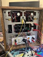
The fan shroud is finished and active cooling running.
Four 60mm fans are inlaid in the cutout that was in the front plate. They are covered by the black shroud that directs the air up over the SITs and sinks.
LM317 control circuit takes power from the main circuit and lowers it for the 12V DC fans. The output voltage is adjustable to tune for noise/performance. The LM317 is sinked to the aluminum mounting plate. I used a hobby knife to split my mica washers into even thinner slices to minimize heat transfer resistance. Added a thin layer of thermal compound to fill any gaps as well.
Air is drawn through the inlets on the backplate and also cool the internals a bit.
Making the fan control PCB currently, and once that’s done I’ll be able to call this project complete (until I decide I want to crank the bias up).
Attachments


@Jerdy... bravo!
You guys are eons ahead of me on the electronic design but from a mechanical and maintenance perspective (working in computer/metrology labs with equipment all using fans) I would recommend you put some kind of air filters upstream of the fans.
Also you might want to put some knurled screws on the front plate so you can service the fans and the filters.
Other than that -and hiding the Bose equalizer- that the best looking amplifier I have seen in eons. Likely ever in my 45 years of audiophile habits... It looks vintage proper with the 2230 and the Teac R2R, except that I'll bet it sounds modern.
That internal metal plate is simple awesome. It is built like a R2R. Did you build the case yourself? You know, if you put some black mesh covers over the transistors, that amp would sit on a shelf in the living room and our Significant Others would actually like them.
IMHO you have found the Mother Lode of domestic amplifier mechanical design.
Last edited:
ra7,
It is time for another one of my questions.
With time I have decided to go with the B- version - Ilike the elegance of the speaker leads on each end of the SIT.
I have also decided to see if the DACs will drive the TDV51. I have the line stage finished but want to see if gain is needed at all first.
The question is: I want to use the CINEMAG transformers for balanced to single ended at the amplifier to get the extra voltage from that connection.
I suspect i am going to need to connect a ground wire from pin one of the DAC to the amplifier but wonder if you would tell me where I would place this? Would it go to the B- rail like the input load resistor or to the positive side of the power supply? Is this something one just has to try for themselves?
Maybe it won't be needed but I suspect it will since I doubt the DAC is a true balanced output.
At you leisure I would appreciate your counsel.
Thanks and take care,

Ha... I see a Marantz Model 2230 back there too. I'm still using one for TV sound.
High praise! I really do appreciate the compliments. I didn't do any circuit design this time around thanks to ra7 and codyt so I went all out on the case to compensate. I have some fine filter mesh I can plaster over the intake vents--definitely a good call.@Jerdy... bravo!
You guys are eons ahead of me on the electronic design but from a mechanical and maintenance perspective (working in computer/metrology labs with equipment all using fans) I would recommend you put some kind of air filters upstream of the fans.
Also you might want to put some knurled screws on the front plate so you can service the fans and the filters.
Other than that -and hiding the Bose equalizer- that the best looking amplifier I have seen in eons. Likely ever in my 45 years of audiophile habits... It looks vintage proper with the 2230 and the Teac R2R, except that I'll bet it sounds modern.
That internal metal plate is simple awesome. It is built like a R2R. Did you build the case yourself? You know, if you put some black mesh covers over the transistors, that amp would sit on a shelf in the living room and our Significant Others would actually like them.
IMHO you have found the Mother Lode of domestic amplifier mechanical design.
Nothing like a little bit of finished wood to make things look vintage. That, and the fact I took direct inspiration from the Teac R2R to guide the design. As for things like thumbscrews, I chose all my fasteners based off what I could get for free through my work. Many of them are products I designed myself for certain electric vehicle OEMs... I can't pass up the opportunity to use some one-of-a-kind screws (and make everything Torx drive)!
The Bose equalizer belongs to my roommate, so I will make sure he is informed 😁
You know, that old style small front, deep chassis came out of the rack mounting school. In this day and age, when components are so much smaller, there is no reason to follow that premise. Even scopes and signal analyzers have become much shallower since they use LED displays and much greater IC IC/ASIC densities. Today's racks in our labs are usually packed with lots of half sized components, rather shallow.
Only server computers, NAS chassis and some aggregation network gear are deep and short (typically no more than 3U).... Heck, depths of 24 and 30 inches are common for those monsters... but I digress.
In audio, we've seen some attempts to break the mold, Bang and Olufsen and Nakamichi, with their receivers, preamps, tuners and cassette decks, come to mind, but it's very hard to break that design ethos. Reel To Reels required the front panel space, so they were shallow... even so the likes of Pioneer released a couple of them in the 79/81 time frame where the front panel was minimized and the depth of the cabinet went up to 12 inches or so.... I guess the use of turntables that required at minimum of a 14" deep shelf defeated the purpose of shallow, but tall, components... and vertical turntables just didn't work so well.
Now... if you could make some room behind that fan cover... put a pair of meters that match the Teac and move the power switch to front.
And, oh.... I admire your cojones in not putting "Obligatory Nelson Pass Blue LED" power indicator.
Now. show us the design of the case and that metal frame you created!
Torx is good. Eons ago some punk stole the driver's side front turn signal indicator off my 94 Acura GSR. It was held by a simple phillips screw. So when I got the replacement, I made a point of replacing all such screws with Torx. They are also mechanically quite strong.
... so your room mate has a pair of Bose 901s hooked up to a Marantz 2235? Is he using a Dual belt drive turntable too with a Pickering 625E cartridge too? Extra points if he's running a Thorens manual belt drive with a Stanton 681EEE.
Only server computers, NAS chassis and some aggregation network gear are deep and short (typically no more than 3U).... Heck, depths of 24 and 30 inches are common for those monsters... but I digress.
In audio, we've seen some attempts to break the mold, Bang and Olufsen and Nakamichi, with their receivers, preamps, tuners and cassette decks, come to mind, but it's very hard to break that design ethos. Reel To Reels required the front panel space, so they were shallow... even so the likes of Pioneer released a couple of them in the 79/81 time frame where the front panel was minimized and the depth of the cabinet went up to 12 inches or so.... I guess the use of turntables that required at minimum of a 14" deep shelf defeated the purpose of shallow, but tall, components... and vertical turntables just didn't work so well.
Now... if you could make some room behind that fan cover... put a pair of meters that match the Teac and move the power switch to front.
And, oh.... I admire your cojones in not putting "Obligatory Nelson Pass Blue LED" power indicator.
Now. show us the design of the case and that metal frame you created!
Torx is good. Eons ago some punk stole the driver's side front turn signal indicator off my 94 Acura GSR. It was held by a simple phillips screw. So when I got the replacement, I made a point of replacing all such screws with Torx. They are also mechanically quite strong.
... so your room mate has a pair of Bose 901s hooked up to a Marantz 2235? Is he using a Dual belt drive turntable too with a Pickering 625E cartridge too?
Extra points if he's running a Thorens manual belt drive with a Stanton 681EEE.
Last edited:
- Home
- Amplifiers
- Pass Labs
- Total Domination VFET (TDV) Amp (using 2SK2087C)