I noticed this Yaqin amp has a transistor for phase-splitter, is this a good solution? Unusual "modern" for a chinese amp?
http://yaqin.slickpepper.org.uk/wp-content/uploads/2008/06/mc-84l_circuit.jpg
Datasheet 2SD669:
http://www.datasheetcatalog.com/datasheets_pdf/2/S/D/6/2SD669.shtml
Arne K
http://yaqin.slickpepper.org.uk/wp-content/uploads/2008/06/mc-84l_circuit.jpg
Datasheet 2SD669:
http://www.datasheetcatalog.com/datasheets_pdf/2/S/D/6/2SD669.shtml
Arne K
Attachments
I'm not enthusiastic about that design, in general.
The BJT is a "concertina" of sorts and should not do too much sonic damage. Perhaps the load is truly split. Still, non-symmetrical resistances in a "concertina" phase splitter raise doubts in my mind.
I don't like the non-symmetrical 12AX7 SRPP voltage gain block at all.
IMO, the design has a "Cheap Charlie" aroma. 🙁
No kidding. And to make things worse, the SRPP uses up a potentially good section of the 12AX7 to no real advantage.
If it were my amp, I'd rewire it for a grounded cathode input stage direct coupled to a split load tube. Because of the high impedance input of the split-load, you can use a CCS on the first stage, which gives you plenty of gain to make the feedback effective. 12AX7 is a better choice than its reputation would suggest as long as the plate load is VERY high, but a 12AT7 would be my first choice there.
Given the slipshod design, you might want to examine the output transformers carefully to see if it's worth trying to polish a turd.
It might almost be easier to just implement a simple/classic 12AT7 directly coupled cathodyne phase splitter. Of course, an amp like that might be built on a board, or have iffy output transformers as some have suggested.
So, if I have an amp with little space, and limited filament-supply, this is still a bad option...maybe I can squeeze in one 6111 sub-mini tube (as gain-stage?).
Arne K
Arne K
You can rework this amp with one 12AT7 per channel. I think you will be ok in terms of filament supply. If you are still hurting, use a single triode and a transformer to minimize filament requirements. How about you post some shots of the inside and transformers.
Cobra2 said:So, if I have an amp with little space, and limited filament-supply, this is still a bad option...maybe I can squeeze in one 6111 sub-mini tube (as gain-stage?).
Arne K
Arne,
The Chinese design you showed SUCKS. However, there is nothing wrong (IMO) with a SS "concertina" phase splitter, to save space and filament power.
DC couple a high voltage enhancement MOSFET to the the common cathode voltage gain tube. Employ identical source and drain resistors of a value appropriate to the ID desired. If a wimpy 12AX7 or similar type is the voltage gain device, use a ZVN0545A as the splitter. Other tube types in the voltage gain "hole" can drive the reverse transfer capacitance of the IRFBC20, which is more capable than the little ZVN0545A.
Thanks for the advice, - it is really for an EL34 amp.
http://www.diyaudio.com/forums/showthread.php?s=&threadid=95667&highlight=
I'm just looking for options, and wondered if it could be an good idea.
I left this amp on the shelf, when I ran out of parts....and now hope to get it running again. I managed to squeeze a couple of ST-70 output irons on top instead of the cut-up-Hyundai and stolen phone-wire OPT's ;-)
Arne K
B.T W.: Any more "common" mosfets I can use?
Received a MC-84L as a xmas present. It's stock. To get this thread rolling again, would like those of you interested, owning, or modding them to show exactly what and how you've done and/or what needs to be done. 😎
base fed from cathode end of srpp resistor is not symetrical use of triodes, but errors to the side of providing needed base current.
I dont see a problem with it.
I dont see a problem with it.
Some Mods:
Could try the Beta-follower on page 126 of Valve Amplifiers, 3rd ed. for the input stage.
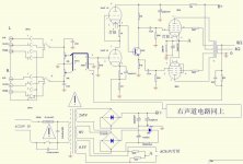
The 2SD669 SS cathodyne splitter has some variation of Hfe versus current. Could be beneficial to try a KSC3503 or 2SC3417 in its place. These have flatter Hfe curves and 5X lower capacitances than the 2SD669. Probably make a better splitter than any tube variant (transconductance is the King here). You might want to tweek the cathodyne load resistors to get exactly equal grid drives for the EL34s. But a little imbalance will just add some 2nd Harmonic. (the reason these resistors are not equal on the schematic is to allow for the tiny additional base current on the lower side, by making the Hfe constant it will not contribute any SS distortion)
Could try the Beta-follower on page 126 of Valve Amplifiers, 3rd ed. for the input stage.
The 2SD669 SS cathodyne splitter has some variation of Hfe versus current. Could be beneficial to try a KSC3503 or 2SC3417 in its place. These have flatter Hfe curves and 5X lower capacitances than the 2SD669. Probably make a better splitter than any tube variant (transconductance is the King here). You might want to tweek the cathodyne load resistors to get exactly equal grid drives for the EL34s. But a little imbalance will just add some 2nd Harmonic. (the reason these resistors are not equal on the schematic is to allow for the tiny additional base current on the lower side, by making the Hfe constant it will not contribute any SS distortion)
Last edited:
Some Mods:
Could try the Beta-follower on page 126 of Valve Amplifiers, 3rd ed. for the input stage.
The 2SD669 SS cathodyne splitter has some variation of Hfe versus current. Could be beneficial to try a KSC3503 or 2SC3417 in its place. These have flatter Hfe curves and 5X lower capacitances than the 2SD669. Probably make a better splitter than any tube variant (transconductance is the King here). You might want to tweek the cathodyne load resistors to get exactly equal grid drives for the EL34s. But a little imbalance will just add some 2nd Harmonic. (the reason these resistors are not equal on the schematic is to allow for the tiny additional base current on the lower side, by making the Hfe constant it will not contribute any SS distortion)
Ahh.. I think I got that. So basically all you're saying is, is replace the 2SD669 with either a KSC3503 or 2SC3417, correct?
I've had a few weeks to let it burn in run it for about 50 hours (off and on), and I'm telling you, compared to vintage all SS Pioneer recievers and my Yaqin VK-2100, this MC-84L has no bass line at all. The mids and tweets are ok after it gets warmed up, but for smooth and deep bass this thing is a am radio so far... Have not done any tube rolling yet.
Something about that SRPP, would seem to balance above B+/2 without load.
There must be expectation of significant base current for concertina to work?
Put in a better transistor may fix that leak and make an impossible operating
point for direct coupling. Voltage above B+/2 makes for no splitter action, all
you would get is base current leaking into the 47K driving one pentode.
You get best headroom with concertina base voltage idling at B+/4.
Cathode resistor in top half of SRPP might need to be increased before
you consider a less leaky transistor. I suspect asymetrical 39K vs 47K
concertina a lame crutch, no proper way to address bad operating point.
Anyways, they got it all backwards, collector resistor should be slightly
the higher value of this concertina if everything else were normal.
Perhaps 50K where you currently see 39K.
Last edited:
Something about that SRPP, would seem to balance above B+/2 without load.
There must be expectation of significant base current for concertina to work?
Put in a better transistor may fix that leak and make an impossible operating
point for direct coupling. Voltage above B+/2 makes for no splitter action, all
you would get is base current leaking into the 47K driving one pentode.
You get best headroom with concertina base voltage idling at B+/4.
Cathode resistor in top half of SRPP might need to be increased before
you consider a less leaky transistor. I suspect asymetrical 39K vs 47K
concertina a lame crutch, no proper way to address bad operating point.
Anyways, they got it all backwards, collector resistor should be slightly
the higher value of this concertina if everything else were normal.
Perhaps 50K where you currently see 39K.
Ken- I read that about 4 times... So what's the fix? Merely replacing a resistor to get the collector resistor to 50K then replacing the transistor?
I dunno: several ways to fix, which is best?
The first issue: You need B+/4 idle voltage for direct couple to base.
Only after that is fixed, use better transistor and 50K sub for 39K.
How you want to drop those extra volts? Looks to me: the top SRPP
triode is gonna have to drop 3x more volts than the lower triode, but
I do not know what top triode cathode resistor will best serve that.
I'd guess 3K? but that guess is based upon linear Gm, not linear Mu.
And we know linear Mu is the stronger rule for triodes, We also do
not know the base current of the transistor at idle, much less what
the new (better less leaky) base current might be?.
Given too many unknowns for my math skill and too lazy to draft a
full LTSpice sim of the situation, I'd abuse a 5K potentiometer in
series with top triode's 1K cathode resistor. Then you can tweak
the base voltage to exactly B+/4.
Last edited:
An entirely different way to direct couple might be at 3/4 B+.
If you went with this operating point, the concertina would
have to be PNP. But this also would reverse the drive phase.
So somewhere else have to flip this back to normal for global
feedback to still work.
If you went with this operating point, the concertina would
have to be PNP. But this also would reverse the drive phase.
So somewhere else have to flip this back to normal for global
feedback to still work.
Last edited:
Smokin amp
Smokin- no such thing as a 2sc3417 at Mouser anymore. 2SC3417
Some Mods:
Could try the Beta-follower on page 126 of Valve Amplifiers, 3rd ed. for the input stage.
The 2SD669 SS cathodyne splitter has some variation of Hfe versus current. Could be beneficial to try a KSC3503 or 2SC3417 in its place. These have flatter Hfe curves and 5X lower capacitances than the 2SD669. Probably make a better splitter than any tube variant (transconductance is the King here). You might want to tweek the cathodyne load resistors to get exactly equal grid drives for the EL34s. But a little imbalance will just add some 2nd Harmonic. (the reason these resistors are not equal on the schematic is to allow for the tiny additional base current on the lower side, by making the Hfe constant it will not contribute any SS distortion)
Smokin- no such thing as a 2sc3417 at Mouser anymore. 2SC3417
For those merely trying the 669 replacement, I got mine all torn apart and there are TWO to replace, not one like the schematic shows.. Either I missed something or...
OK, maybe you got mystery PNP driving an NPN (Sziklai pair).
We have already noted the idle voltage is likely above B+/2.
Maybe its splitting with a PNP emitter toward the high side?
If its NPN+NPN (Darlington Pair) then I got no idea how this
could ever be leaky enough to drag the idle bias below B+/2?
An NPN concertina cannot function with Base above B+/2.
Makes no better sense than a single NPN for same reason,
absurd operating point.
Can you see: are transistors the same markings or different?
Perhaps they gave up on concertina and went with a long
tail pair of NPNs? Input voltage above B+/2 would not upset
a long tail pair.
Last edited:
- Status
- Not open for further replies.
- Home
- Amplifiers
- Tubes / Valves
- Transistor phase splitter (Yaqin MC-84L)