I wanted to make a Triac switch control for a power amp build and would like to know if my thinking is correct and whether it's a sensible idea. I understand some high end manufacturers are using Triac power control.
The Triac.gif schematic attached below was found online and it looked suitable for an amplifier inductive load. It shows an optocoupler triggering the triac via a DC switch.
I planned to use an AMB Power switch board (schem below) and trigger the optocoupler via the AMB board relay control circuit (All thermal cutout components will be omitted) The switch board is handy as it has PS supply and switched regulated output all in one.
- could someone help me choose the correct spec optocoupler and triac please. Will these do for a 250VA power supply 240V AC:
Optocoupler (250V, 50mA, No zero crossing): Vishay K3010P
Triac (400V, 15A 50-50-50mA): Littlefuse Q4015L5
- Can the optocoupler DC input be 5 - 12V range?
- Should there be a fuse or diode protection on the AC ground line to protect the Triac?
- The load can be on either the hot or ground lines?
- Will zero crossing optocouple provide a 'soft start' for this type of load, or not suitable?
Hope that's clear. Thanks
Attachments
These opto triacs have a low load current.
You will need to use the opto triac to drive a high current triac to turn ON/OFF the transformer load.
You should also consider whether you want to use a soft start to allow you to use a close rated mains fuse rather than one rated at 3times the rated transformer primary current.
One big advantage to using triacs is the use of low voltage at the switch.
This allows low voltage type switches to be used and also allows low EMI cabling to be used.
I use a little 5VA transformer that powers up my starting and soft start mechanical relays. The switching loop also includes an overtemp switch to power OFF, if the heatsink gets >70°C
Your first circuit is not bad but place the load on the Hot feed and you MUST use a zero crossing triac if you want to switch an inductive load. A BTA08-600 is gate sensitive, (5mA) and tab is isolated for safety and ease of mounting.
Last edited:
you MUST use a zero crossing triac if you want to switch an inductive load.
Why ?
Your first circuit is not bad but place the load on the Hot feed and you MUST use a zero crossing triac if you want to switch an inductive load. A BTA08-600 is gate sensitive, (5mA) and tab is isolated for safety and ease of mounting.
Excellent, thank you Jon. I had presumed zero crossing was more for resistive loads that are sensitive to start surges.
BTA08-600 looks good thanks.
These opto triacs have a low load current.
You will need to use the opto triac to drive a high current triac to turn ON/OFF the transformer load.
You should also consider whether you want to use a soft start to allow you to use a close rated mains fuse rather than one rated at 3times the rated transformer primary current.
One big advantage to using triacs is the use of low voltage at the switch.
This allows low voltage type switches to be used and also allows low EMI cabling to be used.
I use a little 5VA transformer that powers up my starting and soft start mechanical relays. The switching loop also includes an overtemp switch to power OFF, if the heatsink gets >70°C
Thank you Andrew. I would love to see a schematic of your start circuit.
Lower rated fuses and switch protection were two of my considerations. As you say the opto cannot take hefty loads.
The advice to use zero crossing switching for inductive loads is incorrect. Switching an inductive load at the zero crossing is the worst possible scenario. Ideally you should apply power at the peak of the cycle for an inductive load but that is often impractical. Random phase switching devices are possibly the best compromise.
Mooly, if one switches a transformer on repeatedly at high mains potential, the transformer goes short circuit due to heat from peak current drawn to magnetize the core.
Have a look at light units for inductive loads, they all have zero crossing triacs for this reason. All my light units I designed and built in the 70' to 90's were zero crossing for that reason.
Take a look at the most popular light controllers from Pulsar, the world leaders, all are suitable for inductive loads and employ zero crossing triacs as do Yamaha with their soft start for larger Power Amplifiers before SMPS units were used.
I agree with your PDF but the triac must switch on smoothly and straight away, usually within 2 - 3volts, not posing a problem to the transformer.
Last edited:
Is the initial impedance of the load a critical factor in whether to zero cross or not? A lot of reading is leaning me towards non zero crossing. I might experiment with both on a 120VA tranny.
Mooly - I see that phase angle control looks very interesting, is something like this usable?
The impedance of the load is 'fixed' when in normal use but becomes modified by the remnant magnetism in the core that is produced when you switch off. When you switch on again, that magnetism effects the initial surge current but after a few cycles its all back to normal again. Until the next time.
If you think of an ordinary mechanical switch, its pot luck where in the cycle switching occurs and the same applies for switching off. This means that on some occasions the switch on surge is massive and at other times its very small. Its random because you have no control over the switch on and switch off points.
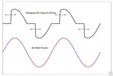
Phase angle control as related to controlling the voltage wouldn't be suitable for a transformer because the shape of the waveform is horrific. Imagine applying that to large transformer.
This shows how it works and what the applied voltage would look like.

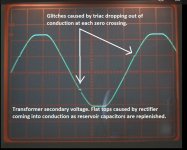
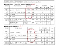
This shows a real glitch caused by using a triac that wasn't rated to fire in all four quadrants (something else to be aware of in choosing a triac) but I'm showing you this because that tiny glitch was enough to make the transformer (a 650 va toroid) very noisy. Not using a suitable triac was my mistake but it was instructive.

Ultimately all you are doing here is replacing a mechanical switch with electronic. The same surge issues still apply and any fuse has to be rated to deal with the worst case surge unless you include a soft start device such as a thermistor.
Jon... not using zero crossing switching for toroids is nothing new, its been the advice from companies involved in this for a long time.
- Can the optocoupler DC input be 5 - 12V range?
Just spotted this from your first post. The opto isolated triac has an infra red LED as its input. This means you need to limit the current into the opto by means of a resistor.
There are dozens of varieties of these opto isolators and its worth checking the data sheet for typical and worst case current values to guarantee correct operation. These might be say 8ma as typical and perhaps 15ma worst case with an absolute maximum of 60ma.
To calculate the resistor value you subtract the LED forward volt drop from the supply and then just use ohms law to derive the resistor value. Typical LED voltage is around 1.3volts for an infra red diode like these. So 5-1.3 gives 3.7 volts to be lost across the resistor. Take the worst case current value of say 15ma and we get a 246 ohm resistor. We could almost certainly be OK with 270 ohm or go one lower and pick 220 ohm which would still be miles within the max rating of say 60ma.
For an inductive load, the preferred switching method is at the voltage peak.
The simplest option is to use an SSR implementing the function, see for example type PS in this document:
http://www.carlogavazzisales.com/pdfs/switchingprod/ssr.pdf
The simplest option is to use an SSR implementing the function, see for example type PS in this document:
http://www.carlogavazzisales.com/pdfs/switchingprod/ssr.pdf
Yes, thank you Elvee. The peak switching relay seems to be made for the job. Trying to find a Carlo Gavazzi RM1C SSR is difficult here.
Mooly - You have been very helpful thank you mate. I know a hell of a lot more now.
Mooly - You have been very helpful thank you mate. I know a hell of a lot more now.
I just gave it as an example: all the big players in this field have similar offers: Omron, Rockwell, Télémécanique, Hitachi,....Yes, thank you Elvee. The peak switching relay seems to be made for the job. Trying to find a Carlo Gavazzi RM1C SSR is difficult here.
Another point to bear in mind. Some large SSR's need a minimum holding current (in other words a minimum load) for them to operate correctly. A large mains transformer lightly loaded (such as a class ab amp idling) may not pull enough current.
Haven't looked and I haven't tried any commercial offerings for real but its something to watch out for.
Haven't looked and I haven't tried any commercial offerings for real but its something to watch out for.
I will have a sketch of the circuit in my notebook (I'm old school)Thank you Andrew. I would love to see a schematic of your start circuit.
Lower rated fuses and switch protection were two of my considerations. As you say the opto cannot take hefty loads.
I'll dig it out and photograph it to post here, later.
How do we avoid this glitch?...............................This shows a real glitch caused by using a triac that wasn't rated to fire in all four quadrants (something else to be aware of in choosing a triac) but I'm showing you this because that tiny glitch was enough to make the transformer (a 650 va toroid) very noisy. Not using a suitable triac was my mistake but it was instructive.
View attachment 524918.................
- Status
- Not open for further replies.
- Home
- Amplifiers
- Power Supplies
- Triac / Optocoupler power switch


