I have a NAD C350 that I picked up for nothing. I am teaching myself how to trouble shoot and repair electronics and I think repairing this amp will be a good project. I have no experience but I am eager to learn.
When I connect speakers and an audio source I get no sound. The speakers work fine when connected to a different amp. The C 350 goes into protection mode when turned on (The power LED light stays red) and nothing makes it to the speakers. The inputs seem to respond normaly. When I select a different input I hear the relays clicking and the corresponding LED turns green. This leads me to think the power supplies are working properly and the problem is somewhere on the amplification side of the unit.
What things should I check first and how should i test them?
What is the DC offset at the input to the speaker relay ?
It will go into protect mode if output has a DC voltage on it above a few hundred millivolts.
It will go into protect mode if output has a DC voltage on it above a few hundred millivolts.
I just looked up checking DC offset and tested it with my multimeter. When I turned on the amp I got 70mV on both speaker outputs. After letting the amp warm up for a few minutes I got 180mV on both speaker outputs. How should I address this?
If the amp is in protect, the relay will be open, so there will be no connection between the speaker outputs/post and the power amp. This is why nigel requested checking the voltage at the input to the relay. Apologies if you have taken the measurement between the emitter resistors, 180mV is doubtful to trip protection.
You could try measuring dc voltage between T101 (or T102) and chassis, repeat for other channel T103(or T104) and GND, these are the bias test points so should be conviently located, they are on the emitters of the output transistors rather than the spkr line.
I measured the suggested test points to ground. After startup I got the following:
T101 -8mV
T102 10mV
T103 10mV
T104 -5mV
After 15 min I got the following:
T101 -2mV
T102 11mV
T103 12mV
T104 0mV
T101 -8mV
T102 10mV
T103 10mV
T104 -5mV
After 15 min I got the following:
T101 -2mV
T102 11mV
T103 12mV
T104 0mV
So those readings indicate no DC problem at output transistor emitters.
2nd check is the power supplies. There are two big cylindrical capacitors. Two terminals are tied together and will read near ground voltage. the two outer terminals should be +- some voltage, typically 50. Not the same voltage on one, report back.
Note do not use two hands to check voltages over 24. >24v across your heart can stop it. Use an alligator clip lead on the meter negative to the speaker ground so that you can measure with only one hand. Wear no jewelry on hands wrists or neck, voltage over 1 at high current though metal can burn your flesh to charcoal.
Sometimes the timing portion of the protection circuit fails. The protection LED being on is an indicator that the timing or DC detect circuit is wrong. Check that +12 or +24 v (depending on the rated voltage printed on it) is across the coil of the protection relay. Not, you'll need a schematic diagram:see electrotanya.com. Although most often on >10 year old units the timing circuit fails because an electrolytic timing capacitor (tens to hundreds of microfarads) is leaking. It has a UPC1237 protection IC, that has 3 inputs, any of the 3 can be wrong.
Other times the protection relay is picked up by the coil, but oxide is preventing the music from flowing through the contacts. Some relays can be cleaned, but most you have to replace them for that problem.
Last edited:
I finished the repair
This thread has been dormant for a while but I have continued to work on this project. Long story short I fixed the amp! Woohoo! If long meandering posts from noobs bumbling around disinterest you stop reading. The sum of all that follows is I fixed it. I am sharing most of what I tried to get it working again so that If someone else is troubleshooting this amp perhaps my post can provide some helpful clues. I also want to thank all those who posted comments. I could not have repaired this without your help.
After my last post in October I decided that some of the trouble shooting tasks left for me were beyond my skill set at that time. I did however observe that some of the power caps had leaked their electrolytic out and the two largest ones were also bulging at the top. I decided to replace all of the electrolytic power capacitors to see if that would fix it. They were clearly bad. Finding suitable replacements for the two largest caps turned out to be a challenge. Although there are plenty of 22000uf 63V caps available, almost none of them will fit inside of the space provided. The original NAD caps are 35mm in diameter and 65mm tall. Most of the 35mm dia caps are much taller than 65mm and would not fit inside of the enclosure. There are some from Myletic, but they are very expensive. Eventually I was able to find some from mouser that were on back order until May. The PN is ESMH630VSN223MA65S. The are a little taller than the originals, but not much. When they finally arrived I ordered the other power caps and caps to replace all of the electrolytics.

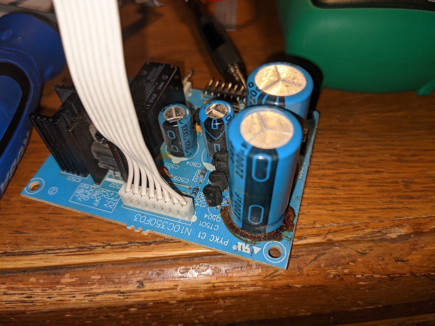
2200uf power caps leaking
Stain under the 2200uf power caps


22,000uf Power Caps leaking


Stain under the large power caps

All Caps replaced

After replacing the power caps and reassembling the amp, It still did not work. I returned to indianajos post and tested the output of all the power supplies.
50 V + and - were good
5.6 V was good
12 V was good
37 V + and - was good
18 V + and - was good
Arrgh. There shouldn’t be a problem. The voltages are good.
Next I took a closer look at the UPC1237 protection IC indianago pointed me toward. I down loaded the datasheet and tested the voltage on every pin.
1.) 0.013V
2.) 0.080V
3.) 0.013V
4.) 2.228V
5.) 0.009V
6.) 45.45V
7.) 0.314V
8.0 3.462V
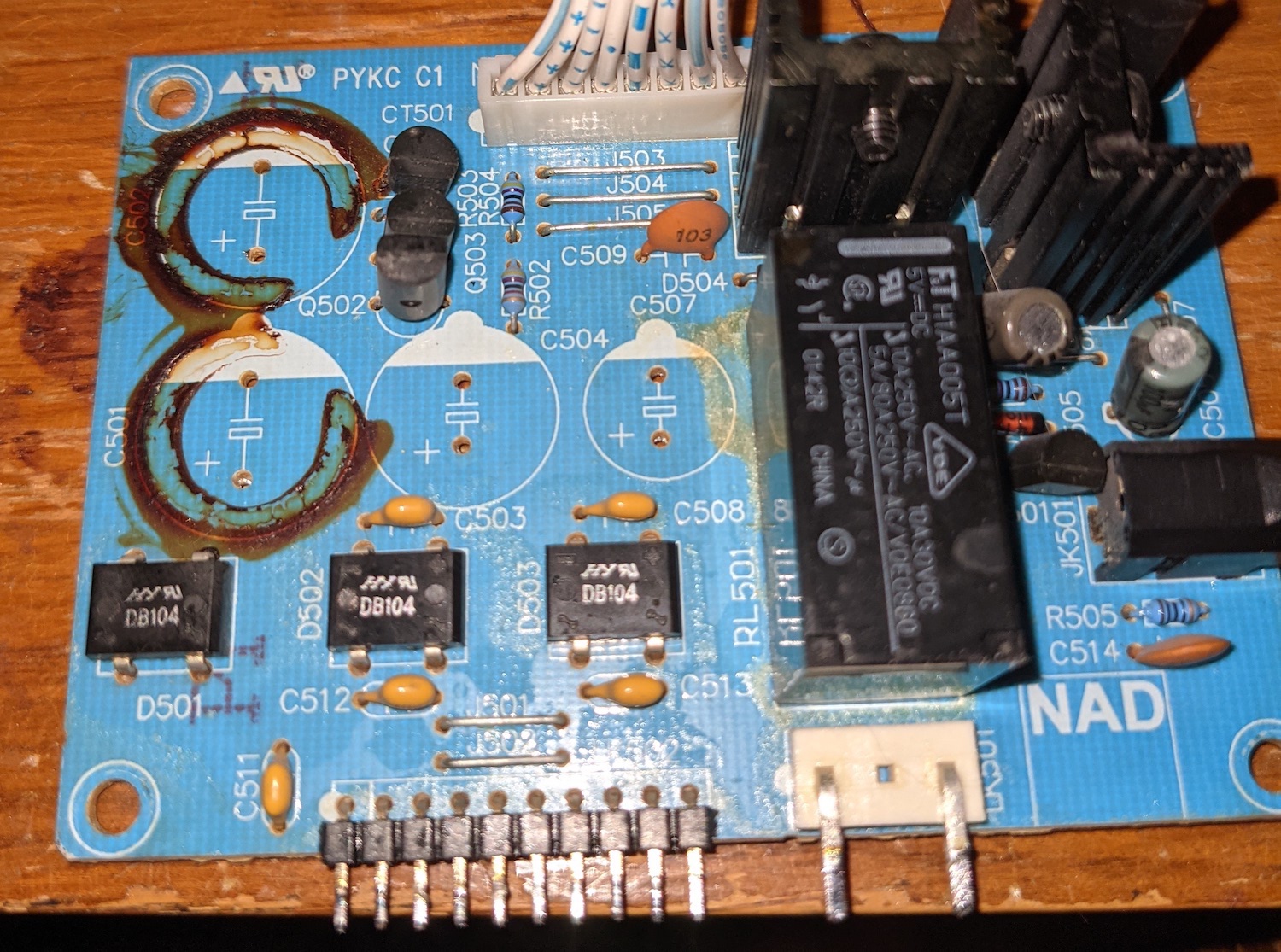
The input for pin 4 was way out of spec. This is what was tripping the protection circuit. Pin 4 is for the ACOFF. I was confused and frustrated I had just replaced the electrolytic caps and the power should have been just fine. Then I found the service change doc that discussed this very problem. C511, C512, and C513 are ceramic caps that fail short and trip the protection circuit.


The recommended replacement caps are metallized polyester film caps. I ordered new caps from digikey, PN DME2P1K-F and installed them. They are considerably larger.


I took the time to test the removed ceramic caps with a DMM and all three tested good. I also tested them with an LCR meter at 120 Hz. The results were as follows:
C511 99.99nf and 570 Kohm
C512 96.05nm and 1.083 Mohm
C513 113,16nf and 2.18Mohm
The replacement caps did test better but I would not have expected the ceramic caps to cause a problem with these values. I would have never found this issue if it were not for the service bulletin from NAD.
When I reassembled and turned on the amp it started working again. What a beautiful sound.
At this point I broke the golden rule of repair work. “If it’s not broke, Don’t Fix It.” I know, I know, I just got it working but I simply couldn’t help myself. I had all of the caps for the rest of the amp so I opened it up again and proceeded to swap them all out. I had chosen caps from good manufacturers, mostly Ryubicon, and I favored ones with the longest rated working life. >5000hrs. I tested all of the caps as I removed the. I am astonished the amp worked at all. Some had less than 1% of their rated capacitance left and only a couple met spec. They all really needed replacing. Once done I followed the Alignment Procedure found in the schematics and buttoned it up again.
It sounds even better now! This amp is going to be a gift for my FIL. I just wanted to see if I could fix it. It has been a very rewarding and at times humbling project, but totally worth it.
This thread has been dormant for a while but I have continued to work on this project. Long story short I fixed the amp! Woohoo! If long meandering posts from noobs bumbling around disinterest you stop reading. The sum of all that follows is I fixed it. I am sharing most of what I tried to get it working again so that If someone else is troubleshooting this amp perhaps my post can provide some helpful clues. I also want to thank all those who posted comments. I could not have repaired this without your help.
After my last post in October I decided that some of the trouble shooting tasks left for me were beyond my skill set at that time. I did however observe that some of the power caps had leaked their electrolytic out and the two largest ones were also bulging at the top. I decided to replace all of the electrolytic power capacitors to see if that would fix it. They were clearly bad. Finding suitable replacements for the two largest caps turned out to be a challenge. Although there are plenty of 22000uf 63V caps available, almost none of them will fit inside of the space provided. The original NAD caps are 35mm in diameter and 65mm tall. Most of the 35mm dia caps are much taller than 65mm and would not fit inside of the enclosure. There are some from Myletic, but they are very expensive. Eventually I was able to find some from mouser that were on back order until May. The PN is ESMH630VSN223MA65S. The are a little taller than the originals, but not much. When they finally arrived I ordered the other power caps and caps to replace all of the electrolytics.

2200uf power caps leaking
Stain under the 2200uf power caps

22,000uf Power Caps leaking

Stain under the large power caps
All Caps replaced

After replacing the power caps and reassembling the amp, It still did not work. I returned to indianajos post and tested the output of all the power supplies.
50 V + and - were good
5.6 V was good
12 V was good
37 V + and - was good
18 V + and - was good
Arrgh. There shouldn’t be a problem. The voltages are good.
Next I took a closer look at the UPC1237 protection IC indianago pointed me toward. I down loaded the datasheet and tested the voltage on every pin.
1.) 0.013V
2.) 0.080V
3.) 0.013V
4.) 2.228V
5.) 0.009V
6.) 45.45V
7.) 0.314V
8.0 3.462V
The input for pin 4 was way out of spec. This is what was tripping the protection circuit. Pin 4 is for the ACOFF. I was confused and frustrated I had just replaced the electrolytic caps and the power should have been just fine. Then I found the service change doc that discussed this very problem. C511, C512, and C513 are ceramic caps that fail short and trip the protection circuit.

The recommended replacement caps are metallized polyester film caps. I ordered new caps from digikey, PN DME2P1K-F and installed them. They are considerably larger.

I took the time to test the removed ceramic caps with a DMM and all three tested good. I also tested them with an LCR meter at 120 Hz. The results were as follows:
C511 99.99nf and 570 Kohm
C512 96.05nm and 1.083 Mohm
C513 113,16nf and 2.18Mohm
The replacement caps did test better but I would not have expected the ceramic caps to cause a problem with these values. I would have never found this issue if it were not for the service bulletin from NAD.
When I reassembled and turned on the amp it started working again. What a beautiful sound.
At this point I broke the golden rule of repair work. “If it’s not broke, Don’t Fix It.” I know, I know, I just got it working but I simply couldn’t help myself. I had all of the caps for the rest of the amp so I opened it up again and proceeded to swap them all out. I had chosen caps from good manufacturers, mostly Ryubicon, and I favored ones with the longest rated working life. >5000hrs. I tested all of the caps as I removed the. I am astonished the amp worked at all. Some had less than 1% of their rated capacitance left and only a couple met spec. They all really needed replacing. Once done I followed the Alignment Procedure found in the schematics and buttoned it up again.
It sounds even better now! This amp is going to be a gift for my FIL. I just wanted to see if I could fix it. It has been a very rewarding and at times humbling project, but totally worth it.
Attachments


Congratulations!
Glad you found the service bulletin about the ceramic caps in the protection circuit. NAD must have found a real bargain on those, ceramic caps are usually forever parts. Voltage analysis would have led you to those parts, but I would have replaced the ceramics last. Be aware meter tests of capacitors don't stress them to the rated voltage, only to 2 volts or so. Most capacitors and semiconductors will withstand 2 volts, but not the higher voltage of the circuit near the rated voltage.
When one electrolytic cap goes bad, I eventually replace them all as all were bought from similar sources of a similar grade (sealant material). If you don't, the remaining caps fail one at a time and the amp is broken all the time. An amp full of new e-caps and maybe a potentiometer or two can last years, just like a new one. However I sound check the circuit after every 2 caps or so to make sure I didn't inject a problem with bad soldering, wrong installation, or wrong part specification. If I do cause a problem, after 2 caps I have a pretty good idea where the problem is - the work I just did.
More complicated amps might be in your future, but I don't recommend repair of televisions or CRT displays. Too many parts go bad all at once, and not economic of my time I have found.
Thanks for this thread! A few weeks ago I decided I'd crack open my C350, which permanently went into protection mode many years ago. Earlier I didn't think it was worthy of the repair (even though I liked it a lot when it worked!), but, well, I changed my mind. I built a guitar amp kit two years ago, so I have most of what I need for tools and materials, even though I still have tons to learn.
Anyway, here we go. I figure I'll replace C511, C512, and C513, as well as the bigger electrolytics. Obviously C501 and C502 (the big ones on the left) at minimum need to be seen to.
Anyway, here we go. I figure I'll replace C511, C512, and C513, as well as the bigger electrolytics. Obviously C501 and C502 (the big ones on the left) at minimum need to be seen to.
Attachments

I've removed most of the power caps, and I've been looking for replacements at digi-key and mouser, but since this is my first try at something like this, I'm not sure if I'm making the right choices. Typically, once I have the capacitance, voltage, and dimensions entered into their filters, I'm left with a few options, and I have no idea how to choose from what's left. I bought this amplifier new and it made it at most 10 years, and it would be nice to do better after this work, assuming I get it going again. Is there any source for parts that I can expect to last longer or somehow perform better in this application, or is it best to just go with what's available from these big suppliers?
Small caps near hot running parts would be the most likely to deteriorate such as those two in the right of your picture.
Always try and fix any fault first before even thinking of replacing a bunch of parts in hope. Just because a cap is old (and ten years is nothing in the scheme of things) doesn't mean it is bad.
Good quality commercial grade parts are perfect, no need to look for anything exotic. Try and choose replacements with a 105C temperature rating over the older more common 85C standard... but diagnose and fix the fault first.
If it was in protection mode then the first test is just to measure the DC offset of each power amp. Both should be close to zero.
A few weeks ago I decided I'd crack open my C350, which permanently went into protection mode many years ago.
Always try and fix any fault first before even thinking of replacing a bunch of parts in hope. Just because a cap is old (and ten years is nothing in the scheme of things) doesn't mean it is bad.
Is there any source for parts that I can expect to last longer or somehow perform better in this application, or is it best to just go with what's available from these big suppliers?
Good quality commercial grade parts are perfect, no need to look for anything exotic. Try and choose replacements with a 105C temperature rating over the older more common 85C standard... but diagnose and fix the fault first.
If it was in protection mode then the first test is just to measure the DC offset of each power amp. Both should be close to zero.
Yes, fix the fault first. DC offset can be measured at the input of the protection relay, if your unit has one. With a protection light on, it probably does.The only e-caps that will cause a protection fault will be around the protection IC, comparitor, or transistor.
Other dired up ecaps will cause low power or weird frequency imbalances. Or in receivers, fuzzy radio, tuning drift, noise. Old .47 to 2 uf e-caps in tuners are particularly temperature sensitive.
When working upgrade two parts at a time, checking in between. If it sounds worse after 2 parts, you know just where the problem is. What you just did.
Instead of 105 c e-caps for household product, I buy electrolytic capacitors rated at 3000 hours service life or over. 12000 hours if I can get it. 105 C parts are okay but there are 500 hour versions sold for cust cutting. Sealant type and water capacity vary between different lines. Digikey & Newark will show you this service life parameter if you ask for it. Mouser makes you download and read each cap's datasheet. I rarely buy from mouser. Note shelf life is different. I will buy caps past shelf life, which can be renewed with a simple charge up at installation with a DC current source.
Brands I use are panasonic nichicon, rubicon vishay kemet. If I can't find anything suitable I'll use united chemicon or cornell dublier. The last two brands had looser ripple specs at end of life than the first five. Times can change, read the datasheets yourself.
When I was buying TV parts store shelf caps before debit cards were invented, I had to change e-caps every 6 years or 12000 hours. B+ voltage and bias voltage would go bad.
Last edited:
Well, given the difficulty of removing the board where C511, C512, and C513 are (these are the caps recommended for replacement in the service bulletin), I replaced all the electrolytics on that board as well. I reassembled and turned on the unit, and it powered up, no protection mode. I adjusted the variable resistors to get 6.0 mV between each pair of test points. Things were going great.
Before trying to test the unit with speakers I thought I should measure DC voltages between those test points and the chassis. Well, while I had the probe on test point T101, I must have slipped, and all four fuses coming off the PT blew.
I received new fuses today, but unfortunately, when I powered up, two of those fuses (both connected to the same rectifier) blew immediately.
I think I had the unit repaired, but I wanted to be thorough, and that little slip seems to have damaged something. I managed to stare at the schematic for a bit and got as far as noticing that those two fuses go to the same rectifier, but after that and a few really not at all enlightening continuity tests, I'm stuck.
That's bad luck 🙁
Most likely you have zapped the output transistors and possibly the drivers as well in the channel effected. If you know exactly what points you shorted you can better judge but those are the most likely.
If you shorted a rail directly to ground you might have shorted a rectifier but that isn't as likely.
Where do you live? I live in the Netherlands and I have two C350s laying around. One with the protection mode issue, the other one with bad power caps and some (repaired) PCB damage. I was thinking of combining them into one nice working unit, but you know how those things go... DM me if you're interested!Well, given the difficulty of removing the board where C511, C512, and C513 are (these are the caps recommended for replacement in the service bulletin), I replaced all the electrolytics on that board as well. I reassembled and turned on the unit, and it powered up, no protection mode. I adjusted the variable resistors to get 6.0 mV between each pair of test points. Things were going great.
Before trying to test the unit with speakers I thought I should measure DC voltages between those test points and the chassis. Well, while I had the probe on test point T101, I must have slipped, and all four fuses coming off the PT blew.
I received new fuses today, but unfortunately, when I powered up, two of those fuses (both connected to the same rectifier) blew immediately.
I think I had the unit repaired, but I wanted to be thorough, and that little slip seems to have damaged something. I managed to stare at the schematic for a bit and got as far as noticing that those two fuses go to the same rectifier, but after that and a few really not at all enlightening continuity tests, I'm stuck.

Thanks for the response! In the attached closeup, you can see how close T101 is to a lead on R190—that would have been the easiest thing to short with my probe. Since I was coming in a bit sideways and from what is "above" in the photo, it's also possible my probe touched R176, but less likely. The rail to the left looks close, but it would have been pretty hard to hit. I scribbled those two possible shorts on a more zoomed-out image of the board, and drew dashed lines for the same two possibilities on the schematic, also included.
Just to be sure my fuses are right: the schematic lists the fuses I blew as as T6.3AL250V-50T-063H. I used Amazon and bought a 10-pack of what are listed as 10Pcs T6.3AL250V 5x20mm 6.3A 250V Slow Blow Fuse T6.3AL Glass Slow-Acting Time-delay Fuse (3/16 in x 3/4 in). I didn't find much with the old google, but the "50T-063H" part on the schematic seems to refer to a Hollyland part number. I'm not sure.
Finally, I included a photo of the transistor Q130 that could be mixed up in this.
Attachments


Why you should use a pomona grabber instead of a meter probe.
I believe those MT200 package transistors were discontinued last year.
One doesn't debug a disaster by looking at the board. One looks at voltages around the place your probe was to see they are correct.
Rather than blowing fuses over & over one inserts some resistance in the AC input line to cut the amount of energy the amp consumes in fault mode. A 60 W tungsten light bulb is the usual device for small amps. I have my bulb socket in a grounded steel box with a circuit breaker ahead of the bulb, and a nice NEMA15 socket for the amp power plug. Those lamp sockets are made for solid house wire, and stranded wire tends to pop off the screw and fly around. Tungsten bulbs can be found at flea markets charity resale shops etc in old lamps. Europeans can use a one cup tea heat element as a resistor, but such appliances do not exist in the western hemisphere.
Last edited:
A short from TP to R190 would probably zap the output transistor. Have you measured them in circuit between C and E and B and E to see if they read short? Measure both output transistors.
Do the same for the drivers Q124 and Q126
The two 0.068 ohm resistors are to low to read on a meter so just make sure they read 'short' and have not gone high or open.
Use a bulb tester rather than keep feeding it fuses.
Do the same for the drivers Q124 and Q126
The two 0.068 ohm resistors are to low to read on a meter so just make sure they read 'short' and have not gone high or open.
Use a bulb tester rather than keep feeding it fuses.
A short from TP to R190 would probably zap the output transistor. Have you measured them in circuit between C and E and B and E to see if they read short? Measure both output transistors.
Do the same for the drivers Q124 and Q126
The two 0.068 ohm resistors are to low to read on a meter so just make sure they read 'short' and have not gone high or open.
Use a bulb tester rather than keep feeding it fuses.
Yeah, and I used Pomona grabbers to adjust the VRs, then switched to the probes for the last bit where I wrecked the amp. Lesson.Why you should use a pomona grabber instead of a meter probe.
I believe those MT200 package transistors were discontinued last year.
One doesn't debug a disaster by looking at the board. One looks at voltages around the place your probe was to see they are correct.
Rather than blowing fuses over & over one inserts some resistance in the AC input line to cut the amount of energy the amp consumes in fault mode. A 60 W tungsten light bulb is the usual device for small amps. I have my bulb socket in a grounded steel box with a circuit breaker ahead of the bulb, and a nice NEMA15 socket for the amp power plug. Those lamp sockets are made for solid house wire, and stranded wire tends to pop off the screw and fly around. Tungsten bulbs can be found at flea markets charity resale shops etc in old lamps. Europeans can use a one cup tea heat element as a resistor, but such appliances do not exist in the western hemisphere.
For me, looking at the board is really more about trying to understand as a non-expert what I'm looking at. Fortunately I have a light bulb limiter I made when I built my guitar amp. For that I used a 600W barn bulb in the socket. That's a pretty responsive tester, but it's what I have on hand for incandescents! Too bad I wasn't using it when I ran those voltage checks. Regrettable.
Checking continuity on the drivers, Q123 and Q125 (on the seemingly unaffected channel) test as open between all of C-E and B-E, but Q124 and Q126 are short between C and E. And on the outputs, Q128 and Q130 are short between C-E and B-E. I'm guessing that both the drivers and the outputs on that impacted channel are kaput. I don't know the role of Q122 and Q121 in this, but I reckon I'll test those as well before I start on a shopping spree. For today, without having put any power through the thing (currently I don't see what would be the point), that's where I'm at. Time to source replacements for the (discontinued but apparently gettable) outputs.
Thanks again for the help and advice. This went from foot race to marathon with one slip of a probe.
- Home
- Amplifiers
- Solid State
- Trouble shooting a NAD C350