

This noise may be caused by a cordless phone or wi-fi device, I hear the idle beacon at fixed rate and the occasional frame exchange. A shield is required if you have high impedence circuits.
Maybe the entire preamp is doing some sort of Earth leakage thing when connected to the Amp. The preamp output if high impedance and could pick up noise.
I don't like the sound of elevated heaters and so on. Be careful it all together is electrically safe for you.
I checked the circuit - it looks OK to me, maybe loose one or two resistors?

I don't like the sound of elevated heaters and so on. Be careful it all together is electrically safe for you.
I checked the circuit - it looks OK to me, maybe loose one or two resistors?
I have just noticed it. Yes indeed! Its the ISP router near to one speaker. Move it further 30cm and its ok now. Perfectly silent on the left channel and a liiiitle bit of hum in the right channel. The one that richgwilliams suggested the problematic wiring. Is anything I can do to improve filtering of the router?This noise may be caused by a cordless phone or wi-fi device, I hear the idle beacon at fixed rate and the occasional frame exchange. A shield is required if you have high impedence circuits.
richgwilliams, what do you suggest to improve right channel wiring? THANK YOU!
You heard the sound. What is the result? How to fix it?Is it a .wav file? Do you have it on a website, send the link?
Jan
The sound of heater and cathode noise is not like thisThanks for you all guys suggestions. I have heaters elevated 90volts.
The presence of R11 makes R22 unnecessary. You only need one 'build out' resistor (cathode stopper), not two.
richgwilliams, what do you suggest to improve right channel wiring? THANK YOU!
Make sure the wiring near R7 is well away from R11, R13, C5 and R16.
Remove R22 and put a wire link in.
Make C5 10uF and a very good capacitor that can isolate a high voltage.
Replace R16 with 47K.
So the ISP router is injecting interference into the speaker wiring. You could try putting small inductors in the preamp output and the speaker wiring see photo:
Also check all wiring, High Voltage DC, AC Line, Elevated heater supply and Earthing. Good Earthing essential for safety.
Glad you found it, good luck.
Thank you rongon and richgwilliams. Will do some changes during weekend and report back.
Regarding this:
Make C5 10uF
Replace R16 with 47K.
Why do you suggest those changes?
Thank you.
Regarding this:
Make C5 10uF
Replace R16 with 47K.
Why do you suggest those changes?
Thank you.
Regarding this:
Make C5 10uF
Replace R16 with 47K.
Why do you suggest those changes?
The value of C5 depends on the input impedance (resistance) of your amplifier. Making R16 47K establishes an output impedance for the preamp and holds the output end of C5 down to Ground at DC. If there was no R16 (or if it was 1000K (1Meg) as in your schematic, when you turn on there would be 160 Volts at the preamp output for a short time.
The 47K resistor ensures that C5 charges up quickly (to have 160 Volts on one side and 0V on the other side) faster than the valve U1 can warm up.
Getting back to C5 lets say you connect an amp with an input impedance of 10K Ohms to your preamp, the time constant (with R16 as 47K as well) would be 8246 *2.2 x 10e-6 which is 18milliSeconds, that would impact the low frequency response of your preamp, 20 Hz would be attenuated. So 2.2 uF is a bit small, it is OK if your amp input is high impedance but 4.7uF would be better and 10uF even better. Its not a big thing, you could leave it as it is, but make sure it can isolate the maximum possible B+ HT (not just 160 Volts).
Also R14 at 470K is a bit high, I would put a 100K resistor for R14. It will establish a good DC level across C3 faster.
As I said before its a nice looking preamp and nicely built. It is a nice circuit with low THD.
The first tube U4 introduces some THD (-50dB for small signals) the Cathode follower U1 introduces no THD.
This noise may be caused by a cordless phone or wi-fi device, I hear the idle beacon at fixed rate and the occasional frame exchange. A shield is required if you have high impedence circuits.
You were very quick to spot that it was sounds produced by a router ! The usual recognisable plague is mobile cellular interference.
That's because I've heard it several times before. Mobile cellular interference sounds different, bursts of noise while the phone is occasionally exchanging data with the remote base station, but no constant ticking beacon. CD/SACD players can also produce audible interference when the laser pickup is moving. A inexpensive SDR receiver is useful to pinpoint a radio interference source and the energy signature.You were very quick to spot that it was sounds produced by a router !
oh. I see. thanks for the detailed explanation.The value of C5 depends on the input impedance (resistance) of your amplifier. Making R16 47K establishes an output impedance for the preamp and holds the output end of C5 down to Ground at DC. If there was no R16 (or if it was 1000K (1Meg) as in your schematic, when you turn on there would be 160 Volts at the preamp output for a short time.
The 47K resistor ensures that C5 charges up quickly (to have 160 Volts on one side and 0V on the other side) faster than the valve U1 can warm up.
Getting back to C5 lets say you connect an amp with an input impedance of 10K Ohms to your preamp, the time constant (with R16 as 47K as well) would be 8246 *2.2 x 10e-6 which is 18milliSeconds, that would impact the low frequency response of your preamp, 20 Hz would be attenuated. So 2.2 uF is a bit small, it is OK if your amp input is high impedance but 4.7uF would be better and 10uF even better. Its not a big thing, you could leave it as it is, but make sure it can isolate the maximum possible B+ HT (not just 160 Volts).
Also R14 at 470K is a bit high, I would put a 100K resistor for R14. It will establish a good DC level across C3 faster.
As I said before its a nice looking preamp and nicely built. It is a nice circuit with low THD.
The first tube U4 introduces some THD (-50dB for small signals) the Cathode follower U1 introduces no THD.
I have a soft start circuit with a relay btw. output connects 58s after power on. I also have a CL thermister in PT primary.
my power amp is high impedance. C5 cap is 630Vdc max.
pscan, any suggestion on how to make a shield to overcome this interference?That's because I've heard it several times before. Mobile cellular interference sounds different, bursts of noise while the phone is occasionally exchanging data with the remote base station, but no constant ticking beacon. CD/SACD players can also produce audible interference when the laser pickup is moving. A inexpensive SDR receiver is useful to pinpoint a radio interference source and the energy signature.
thank you
oh. I see. thanks for the detailed explanation.
I have a soft start circuit with a relay btw. output connects 58s after power on. I also have a CL thermister in PT primary.
my power amp is high impedance. C5 cap is 630Vdc max.
That's impressive! With those arrangements I would leave C5 alone as 2.2uF and 630 VDC also I would leave R16 out altogether as long as your amp input will establish a stable DC level across C5.
Your preamp is a good design hard to improve on it. The only comment would be - if you increase R21 in the Cathode of U4 from 470R to 1K0 it will improve the THD and reduce gain by about half, worth doing if your system can work with the preamp gain reduced by half.
Valve circuitry is always very forgiving at switch on. The valves are all open circuit and gradually start to conduct as the heaters warm up. It gives time for decoupling capacitors to charge up.
In the past I have seen commercially produced record player amps (hi-fi?) that go from phono to a few Watts output using only one valve (usually Triode and Tetrode inside) and very few other components.
PS This circuit would work just as well for the Cathode follower at lower B+ HT and it defines the voltage seen by the 2u2 630 VDC output capacitor (at about half B+):

I was measuring Vdc at the output and I saw that it takes more than 58s to stabilize.
And even after that, it fluctuates a lot, between -100mVdc to 100mVdc. May be I should decrease R16 after all. Shouldn't I?
And even after that, it fluctuates a lot, between -100mVdc to 100mVdc. May be I should decrease R16 after all. Shouldn't I?
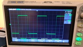
Measure (with preamp input shorted) at the point where R11, R13, C5 and R14 join with a scope. Measure with and without your amplifier connected to the preamp output.
If there is the same noise check what frequency it is maybe it is the 50/60 Hz line frequency coming from the B+ HT. its hard to filter it all out in the power supply.
The slow drift (58s) is probably the valve warming up settling your circuit at the moment has a somewhat undefined DC level where R11, R13, C5 and R14 join. That's part of the reason I was mentioning the follower circuit in post #37.
As the circuit is now, if you have no output connected and R16 really is 1 Meg Ohm and R22 is 2.2 uF just those two components will take most of 10 seconds to settle.
Then with R14 at 470K and C3 at 2.2uF those two components will take most of 5 seconds to settle. So the rest of the 58 seconds must be the valve warming up and maybe the power supply ramping up B+ HT.
Suggest you make R16 100K and R14 100K. Also consider trying the follower circuit in post #37. For that circuit you can leave B+ HT at 275 Volts or reduce to 200 Volts. With that circuit current through U1 Anode to Cathode is about 6mA so even at B+ of 275 Volts dissipation is less than 1 Watt. For that circuit the heater should be at half of B+
According to my experience, the way this issue has been dealt in the past does work. To shield the components inside the chassis, I use a fully enclosed metal chassis with many screws closing the metal bottom lid. I attach potentiometers and connectors directly to the chassis, this way radio frequency cannot enter trough holes or open slots. Front and rear panels, when they are needed to conceal screws, are attached to the chassis with short spacers at the four corners. Interference also enters trough the exposed tubes. I use tube shields to cover standard tubes such as ECC83; or internally shielded tubes that have been designed as dual diode plus triode or pentode audio amplifier stage for radio receivers. They are nice tubes meant to amplify small audio signals, so they are linear, with little or no microphonics, and almost no mains hum leaking from the filament. And most of them are internally shielded, external shield is not needed. If exposed tubes aren't required, I've found very effective the kind of construction that was popular in the early 1960's: tubes mounted horizontally on a internal vertical support (or PCB) that runs from side to side of the chassis.pscan, any suggestion on how to make a shield to overcome this interference?
thank you
- Home
- Amplifiers
- Tubes / Valves
- Tube amp noise