
Hi,
there are spare boards but the first group buy for the components is full. I can add you to the second batch but probably looking like mid - end of May.
If you want to go ahead could fill out this Google Form I will send you a PayPal invoice with the deposit amount.
there are spare boards but the first group buy for the components is full. I can add you to the second batch but probably looking like mid - end of May.
If you want to go ahead could fill out this Google Form I will send you a PayPal invoice with the deposit amount.
Hi, I am still waiting for the PCB's and two final components to arrive. The PCB manufacturer is in China and they have had problems with delays due to Covid and then issues with shipping. In fact the first shipment of boards was lost in transit and they had to be remade. (The PCB fab were reluctant to do this until 2 week period had passed). I have paid extra to have them shipped by DHL to try and make up time. I had hoped to have started shipping by mid/end April (see post #46) but with the PCB delays I think it will now be early/mid May. 🙁
I will post here on the thread as the final items arrive and then give a better idea of the ETA. Apologies, this is going to be slightly longer than original mid/end April estimated.
I will post here on the thread as the final items arrive and then give a better idea of the ETA. Apologies, this is going to be slightly longer than original mid/end April estimated.
Any date to start shipping the first group? Thanks
SB
Hi. No problem, thanks for all your work. In the mean time I found a brand new LP12 motor with pulley...
SB
SB
... Apologies, this is going to be slightly longer than original mid/end April estimated.
No worries, more time for planning! 🙂
I'm still thinking about the various packaging options:
- Every inside the turntable
- Main PCB, display and on/off switch in an external box, sensor on the turntable
- Main PCB in an external box, on/off switch, sensor and display on the turntable
From a pic you posted:
Disregarding AC in 110/220V, can we reasonably assume there'd be:
- 3 wires to the motor
- 3 wires to the sensor
- 2 wires to the on/off switch, possibly 1 of which is common to the sensor
For the wiring, I'm thinking of the "aviation connectors" such as these:
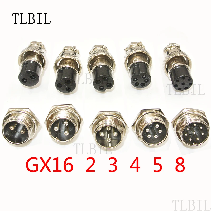
While they're rated to 250V/5A, I'm moderately concerned because the chassis part is male with the pins exposed, while the cable part is female. Do you have a protection circuit for the power transistors?
Last edited:
We'll be patient, Scobham. The unusual circumstances and all.
Thanks!
I second that Peter.
Steve is doing is utmost to get the build out asap.
Regards
Ray.
Hello fellow DIYers….an update.
Firstly thank you for the comments of support (and patience).
So the PCB’s are now in DHL’s distribution warehouse in Germany so hopefully it won’t take much longer for them to reach me. The two parts still outstanding are the PSU chip and the power output transistor heatsinks.
I can at least start the SMD assembly phase for those of you who have ordered the fully assembled kits as soon as the PCB's are here. I don’t need the PSU chip and heatsinks to start that.
I have 1 page left to write on the combined assembly, installation, setup and tuning manual. This has turned out to be a mammoth task. I hit page 60 mark yesterday. Don’t worry a lot of it is colour pictures of the assembly process and background theory if you want to tinker with all of the various configuration parameters and PID settings. The boards will ship with defaults which will get you going quickly plus I have the parameters worked out exactly for several turntables (LP12 users that’s you). You can use the default PID parameters on any turntable to get going. It’s just you may be able to improve start-up/change speed times to exact rotation quicker than the 8 seconds ;-) if you tune it to your individual setup. By the way it’s the test point voltages that are the final 1 page.
Answering ZUNG’s questions are relevant to a wider audience. I also looked at the Aviation connectors for the external 3D printed enclosure I posted in #110 but I rejected them as only male chassis pinned versions are available – please do not use them. (Remember the PSU is does not provide isolation so you need to ensure your enclosure is safe). I think I have located a low cost 6 pin female chassis connection – I have ordered one off ebay to check as the diagrams are not clear (still waiting 5 weeks for it). It supposedly only needs a 13mm hole to chassis mount so looks ideal. Here it is (its not really an Aviation connector despite the title):
SP13 Waterproof IP68 Chassis Panel Mount Circular Aviation Plug Cable ConnectorS | eBay
Regarding output transistor protection – yes its fine to run the board without the motor load. The motor windings connect via a capacitor so there is no DC on the connector (but there is 6-110v AC rms depending on what you set for your motor).
Motor drive is a minimum of 3 wires (you can share the common GREY of each phase) but you may need to cater for Earth depending on your turntable. If housing the controller in an external box you could also alternatively, feed the supply back to the controller if you want to use the main turntable power switch as a master on/off so 2 more conductors could optionally be required.
For the final boards I have added an 8 way 1mm FFC connector for the combined OLED/Switch/LED/IR sensor connection as it offers the thinnest, easiest, unobtrusive connection method. (The resistors and transistors are all SMD now rather than a mix of SMD and through hole). Don’t worry if you are building your own kits, I am going to solder that 1mm pitch FFC connector on the board for all of you with my IR reflow oven as they are not easy to hand solder. (I did baulk at the even smaller 0.5mm pitch version). There is still the original 0.1” pin header connection available as well if you prefer to use that in your own external enclosure combinations. I attach a wiring diagram at your request Zung to you can see how many signal lines are required.
If any of you are considering Pyramid’s NIXIE display, the Motor Controller USB serial output is compatible. I have agreed to co-ordinate the pre-programmed microprocessor outside of the US.
I will post further updates as soon as I have more news.
Keep well and I hope you are all OK in these unusual times.
Attachments


Last edited:
...
I think I have located a low cost 6 pin female chassis connection – I have ordered one off ebay to check as the diagrams are not clear (still waiting 5 weeks for it). It supposedly only needs a 13mm hole to chassis mount so looks ideal. Here it is (its not really an Aviation connector despite the title):
SP13 Waterproof IP68 Chassis Panel Mount Circular Aviation Plug Cable ConnectorS | eBay
...
I've found the WS16 series: I think they're nice too, and they're fully specified: 400V, 5A, and up to 10 pins; technical drawing is at the link. Chassis side is female, and cable side is male. The only catch is you need a 16.5mm hole punch/saw.

Edit
Here's the specs for the SP13:


Last edited:
Hi Zung,
Those specifications are helpful. The problem with the Chinese SP13 listings on eBay is that the do no clearly specify which gender of the pieces they are supplying as standard.
I have found these SP13 6 pin connectors from a UK supplier called CPC. As you would expect they are more than double the price of the ebay ones (plus delivery) but they are clearly specified and available.
If there is interest I am willing to organise a mini group buy for them (SP13) and we can spread the postage costs. The connectors are 3.29 (inc tax) for each half. Delivery is free if we get over 20 GBP. Any takers? Start a mini GB list below. As usual copy and paste the whole list and add your name to the end.
hello all, and scobham way to go!
not sure whether this has been discussed before,is there a convenient way to raise the printed speed sensor box if needed?what is the current sensor height from turntable base? thanks
not sure whether this has been discussed before,is there a convenient way to raise the printed speed sensor box if needed?what is the current sensor height from turntable base? thanks
Hi there geoturbo,
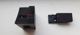
currently there are two IR sensor options. 1) in the combined IR sensor/OLED/switch casing. That’s the wedge shaped box and is designed to fit somewhere next to the platter. The IR sensor is a rectangle 10x5mm centred about 18mm from the top of the plinth 2) IR sensor on the inside of the platter. This is only suitable for platters which have sufficient clearance e.g. LP12 and probably TD160 – there could be others though. With option 2) you need to decide somewhere for the OLED and switch (possibly an external enclosure) – see post #110 or some alternatives Zung and others have suggested. (Attached image has the combined speed box standing on end so you can see the IR aperture. Image on the right is the casing when mounting the sensor inside/under the platter).
Inevitably, the IR sensor 3D printed boxes will not fit all turntables. Either radius, positioning or height will be a problem and I cannot make a box for every turntable variation in advance. I will make available the Fusion 360 CAD (Fusion 360 is free for personal use) design for anyone who wants to modify it to fit their turntable. All I would ask is you send me a copy of the modified CAD file with the turntable details. I will even print the box for you for cost of filament (about 0.50 GBP) and postage. Although the design is heavily modified, I must credit Greggan with the original combined speed box concept. Send me a PM if you want the file.
Incidentally, remember you can always use a Hall effect sensor & magnet if the IR sensor is not suitable for your turntable. An example of this might be a highly chromed platter with limited space inside the platter for IR sensor mounting. I am currently investigating reversing the logic on the sensing and using the reflectivity of the polished chrome platters and using a matt black marker label instead of white markers.
hello all, and scobham way to go!
not sure whether this has been discussed before,is there a convenient way to raise the printed speed sensor box if needed?what is the current sensor height from turntable base? thanks
Attachments
Last edited:
thank you for your thorough reply Scobham, and endless availability.
I am with option 1) IR sensor/OLED/switch casing for my Nottingham Analogue Spacedeck. Expected final height of the IR sensor is about 90mm. I'll be glad if you could share the cad file, pm's on the way.. thanks a lot,
Matt.
I am with option 1) IR sensor/OLED/switch casing for my Nottingham Analogue Spacedeck. Expected final height of the IR sensor is about 90mm. I'll be glad if you could share the cad file, pm's on the way.. thanks a lot,
Matt.
Supply
Just a thought Steve, could your design transfer to a Raspberry Pi? They are now manufactured by Sony, here in the uk- Bridgend, Wales to be exact.
I understand the the convenience of Arduino but in reality the packaging won't be that much bigger - not to mention the extra functionality; this would open your product up to dc motor enthusiasts.
Best regards,
Nigel
Hi Nigel,
thanks for the post. Well its taken almost 12 months to get the code developed, debugged and stable and three revisions of PCB's to get to a error free design that works and has a multitude of options. I have to say I have very little appetite to port to a different hardware platform 😱 Driving DC motors could be done with the Arduino as it stands today. but would require different output circuitry - that would be an easier option than a port to a different microprocessor platform. Maybe once I get some energy back after the group buy is finished I will give it some thought. 😉
What does the community think? is there a demand?
Just a thought Steve, could your design transfer to a Raspberry Pi? They are now manufactured by Sony, here in the uk- Bridgend, Wales to be exact.
I understand the the convenience of Arduino but in reality the packaging won't be that much bigger - not to mention the extra functionality; this would open your product up to dc motor enthusiasts.
Best regards,
Nigel
- Home
- Group Buys
- Turntable Tachometer and motor speed controller